 |
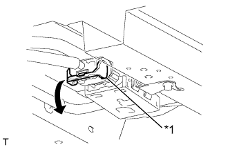
Turn the lock lever and disconnect the connector of the fuel pump ECU.
| *1 | Lock Lever |
OIL PUMP > REMOVAL |
| 1. DISCHARGE FUEL SYSTEM PRESSURE |
Disconnect the cable from the negative (-) battery terminal.
|
Turn the lock lever and disconnect the connector of the fuel pump ECU.
| *1 | Lock Lever |
Connect the cable to the negative (-) battery terminal.
Start the engine. After the engine has stopped on its own, turn the ignition switch off.
Crank the engine again, then check that the engine does not start.
Loosen the fuel tank cap, then discharge the pressure in the fuel tank completely.
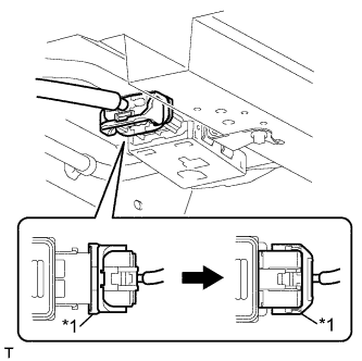 |
Connect the connector of the fuel pump ECU.
Turn the lock lever and secure the connector with the lock lever.
| *1 | Lock Lever |
| 2. PRECAUTION |
| 3. DISCONNECT CABLE FROM NEGATIVE BATTERY TERMINAL |
| 4. DRAIN ENGINE OIL |
Remove the oil filler cap.
Remove the oil pan drain plug and gasket, and drain the engine oil into a container.
Install a new gasket and the oil pan drain plug.
| 5. DRAIN ENGINE COOLANT |
Loosen the radiator drain cock plug.
Remove the radiator cap. Then drain the coolant from the radiator.
Loosen the 2 cylinder block drain cock plugs. Then drain the coolant from the engine.
Tighten the 2 cylinder block drain cock plugs.
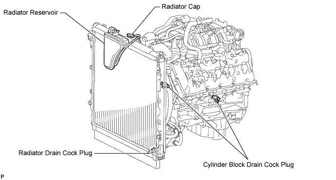
Tighten the radiator drain cock plug by hand.
| 6. REMOVE RADIATOR ASSEMBLY |
Remove the radiator (Click here).
| 7. REMOVE INTAKE MANIFOLD |
Remove the intake manifold (Click here).
| 8. REMOVE AIR SWITCHING VALVE ASSEMBLY (for Bank 1) |
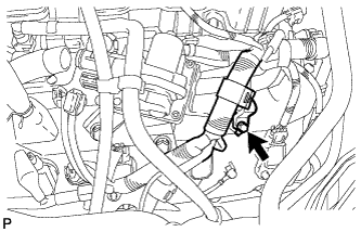 |
Remove the bolt and disconnect the wire harness clamp bracket.
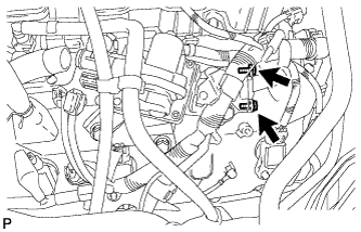 |
Remove the 2 bolts.
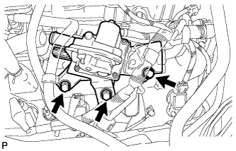 |
Remove the 3 bolts, air switching valve and gasket.
| 9. DISCONNECT NO. 1 AIR HOSE |
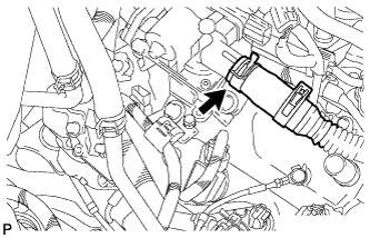 |
Disconnect the No. 1 air hose.
| 10. REMOVE AIR SWITCHING VALVE ASSEMBLY (for Bank 2) |
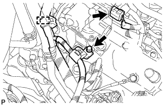 |
Disconnect the connector and clamp.
Remove the bolt and disconnect the wire harness clamp bracket.
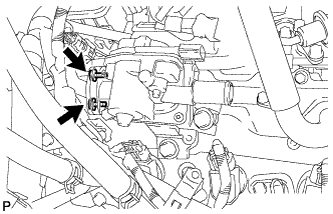 |
Remove the 2 bolts.
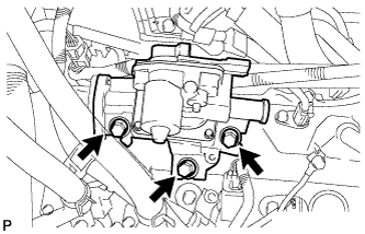 |
Remove the 3 bolts, air switching valve and gasket.
| 11. DISCONNECT ENGINE WIRE |
Engine Room LH Side:
Remove the engine room relay block cover.
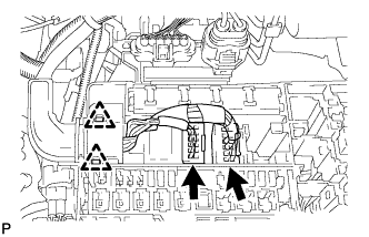 |
Disconnect the 2 connectors and detach the 2 clamps from the engine room junction block.
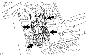 |
Disconnect the 4 air injection control driver connectors.
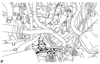 |
Disconnect the 2 wire harness clamps.
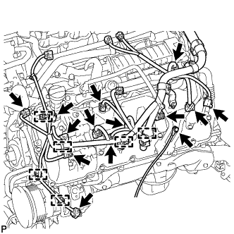 |
Disconnect the injector connector.
Disconnect the 4 ignition coil connectors.
Disconnect the 2 VVT sensor connectors.
Remove the bolt and ground wire.
Disconnect the noise filter connector.
Disconnect the engine coolant temperature sensor connector.
Disconnect the 2 camshaft timing oil control valve connectors.
Disconnect the camshaft position sensor connector.
Disconnect the 6 clamps.
Disconnect the cooler compressor connector.
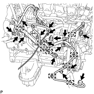 |
Engine Room RH Side:
Disconnect the 2 camshaft timing oil control valve connectors.
Disconnect the 4 ignition coil connectors.
Disconnect the injector connector.
Disconnect the 2 VVT sensor connectors.
Disconnect the noise filter connector.
Remove the bolt and ground wire.
Disconnect the 2 air pump connectors.
Disconnect the 9 clamps.
Disconnect the power steering oil pressure switch connector and solenoid valve connector.
for 4WD:
Disconnect the clamp and junction connector.
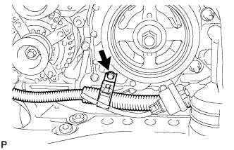 |
Remove the bolt and disconnect the bracket.
| 12. DISCONNECT NO. 3 AIR INJECTION SYSTEM HOSE |
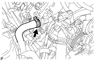 |
Disconnect the No. 3 air injection system hose.
| 13. DISCONNECT HEATER HOSE AND NO. 1 WATER BY-PASS PIPE |
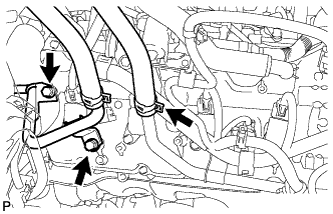 |
Disconnect the heater hose.
Remove the 2 bolts and disconnect the No. 1 water by-pass pipe.
| 14. DISCONNECT COOLER COMPRESSOR ASSEMBLY |
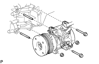 |
Remove the 2 bolts, 2 nuts and 2 stud bolts, and disconnect the cooler compressor.
| 15. REMOVE OIL FILTER ELEMENT |
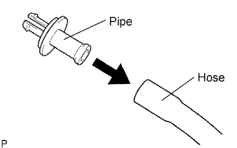 |
Connect a hose with an inside diameter of 15 mm (0.591 in.) to the pipe.
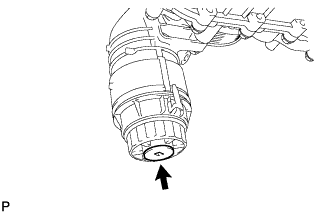 |
Remove the oil filter drain plug.
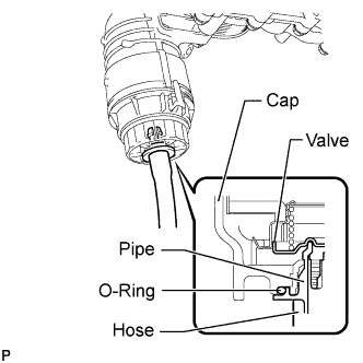 |
Install the pipe to the oil filter cap.
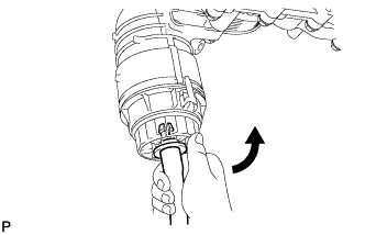 |
Check that oil is drained from the oil filter. Then disconnect the pipe and remove the O-ring, as shown in the illustration.
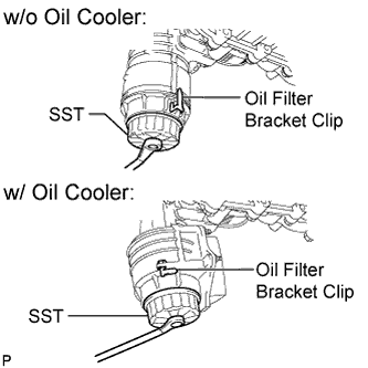 |
Using SST, remove the oil filter cap.
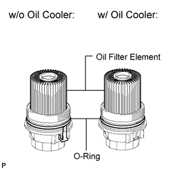 |
Remove the oil filter element and O-ring from the oil filter cap.
| 16. REMOVE OIL PRESSURE SENDER GAUGE ASSEMBLY |
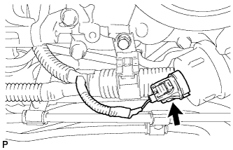 |
Disconnect the sender gauge connector.
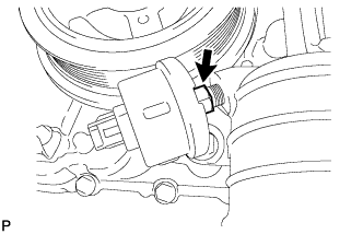 |
Remove the oil pressure sender gauge.
| 17. REMOVE WATER BY-PASS PIPE (w/ Oil Cooler) |
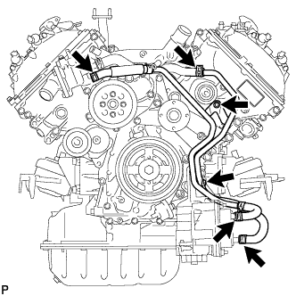 |
Remove the 2 bolts.
Disconnect the 4 hoses and remove the water by-pass pipe.
| 18. REMOVE NO. 1 OIL COOLER BRACKET (w/ Oil Cooler) |
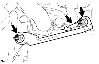 |
Remove the 2 nuts and bracket.
Disconnect the ground wire from the cylinder block.
| 19. REMOVE OIL FILTER BRACKET |
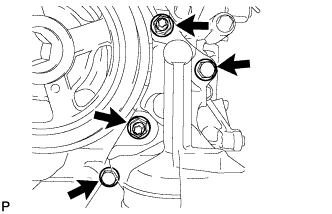 |
Remove the 2 bolts, 2 nuts and filter bracket.
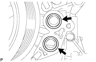 |
Remove the 2 O-rings.
| 20. REMOVE ENGINE OIL LEVEL DIPSTICK GUIDE |
Remove the dipstick.
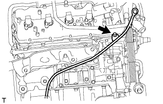 |
Remove the bolt and dipstick guide.
Remove the O-ring from dipstick guide.
| 21. DISCONNECT VANE PUMP ASSEMBLY |
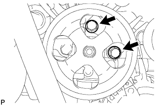 |
Remove the 2 bolts and disconnect the vane pump.
| 22. REMOVE GENERATOR ASSEMBLY |
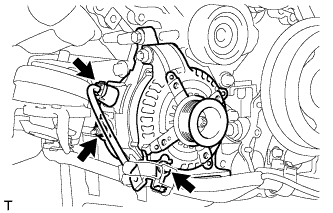 |
Remove the terminal cap.
Disconnect the generator connector.
Remove the nut and disconnect the generator wire.
Remove the bolt and disconnect the wire harness bracket from the generator.
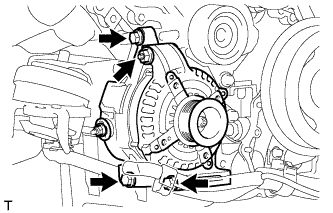 |
Remove the 3 bolts, nut and generator.
| 23. REMOVE NO. 4 ENGINE COVER |
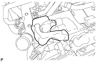 |
Remove the No. 4 engine cover.
| 24. REMOVE NO. 3 ENGINE COVER |
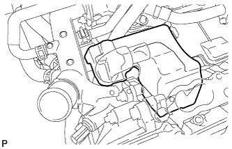 |
Remove the No. 3 engine cover.
| 25. REMOVE NO. 1 WATER BY-PASS HOSE |
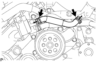 |
Remove the water by-pass hose.
| 26. REMOVE AIR TUBE SUB-ASSEMBLY RH |
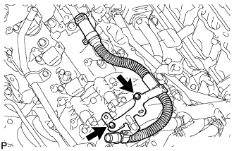 |
Remove the 2 bolts and air tube.
| 27. REMOVE WATER BY-PASS PIPE SUB-ASSEMBLY |
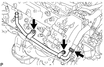 |
Disconnect the hose.
Remove the 2 bolts and water by-pass pipe.
| 28. DISCONNECT NO. 8 WATER BY-PASS HOSE |
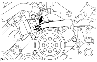 |
Disconnect the water by-pass hose.
| 29. DISCONNECT NO. 5 WATER BY-PASS HOSE |
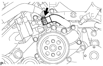 |
Disconnect the water by-pass hose.
| 30. REMOVE WATER INLET HOUSING |
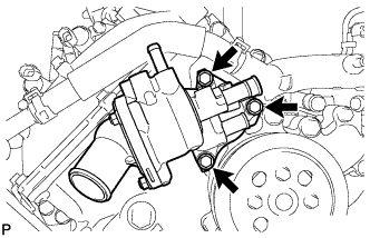 |
Remove the 3 bolts, water inlet housing and gasket.
| 31. REMOVE FRONT WATER BY-PASS JOINT |
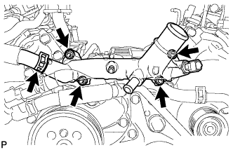 |
Remove the No. 2 water by-pass hose from the water by-pass joint.
Remove the 4 nuts, water by-pass joint and 2 gaskets.
| 32. REMOVE WATER PUMP PULLEY |
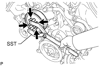 |
Using SST, hold the water pump pulley.
Remove the 4 bolts and the water pump pulley.
| 33. REMOVE NO. 1 IDLER PULLEY SUB-ASSEMBLY |
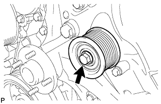 |
Remove the bolt and idler pulley.
| 34. REMOVE FAN BRACKET ASSEMBLY |
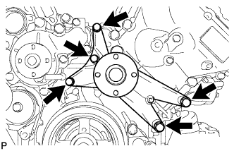 |
Remove the 5 bolts and fan bracket.
| 35. REMOVE V-RIBBED BELT TENSIONER ASSEMBLY |
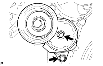 |
Remove the bolt, 6 mm hexagon bolt and belt tensioner.
| 36. DISCONNECT NO. 4 AIR TUBE |
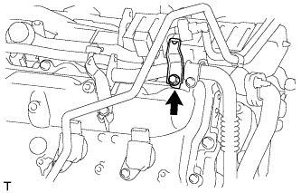 |
Remove the bolt and wire harness clamp bracket.
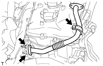 |
Remove the bolt and 2 nuts, and disconnect the No. 4 air tube.
Remove the gasket from the No. 4 air tube.
| 37. DISCONNECT NO. 3 AIR TUBE |
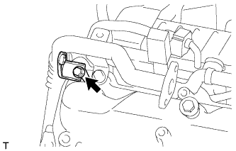 |
Remove the bolt and wire harness clamp bracket.
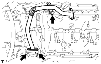 |
Remove the bolt and 2 nuts, and disconnect the No. 3 air tube.
Remove the gasket from the No. 3 air tube.
| 38. REMOVE IGNITION COIL ASSEMBLY |
Remove the 8 bolts and 8 ignition coils.
| 39. REMOVE CYLINDER HEAD COVER SUB-ASSEMBLY LH |
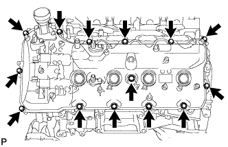 |
Remove the 14 bolts, seal washer, cylinder head cover and gasket.
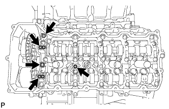 |
Remove the 5 gaskets from the camshaft bearing caps (No. 2, No. 3).
| 40. REMOVE CYLINDER HEAD COVER SUB-ASSEMBLY RH |
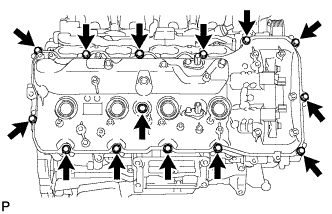 |
Remove the 14 bolts, seal washer, cylinder head cover and gasket.
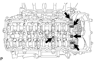 |
Remove the 5 gaskets from the camshaft bearing caps (No. 1, No. 3).
| 41. REMOVE CRANKSHAFT PULLEY |
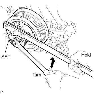 |
Using SST, remove the crankshaft pulley set bolt.
Temporarily install the pulley set bolt to the crankshaft until 2 or 3 threads are engaged.
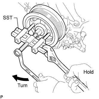 |
Using the pulley set bolt and SST, remove the crankshaft pulley.
| 42. REMOVE TIMING CHAIN COVER SUB-ASSEMBLY |
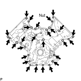 |
Remove the 26 bolts and nut shown in the illustration.
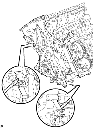 |
Remove the timing chain cover by prying between it and the cylinder head and cylinder block with a screwdriver as shown in the illustration.
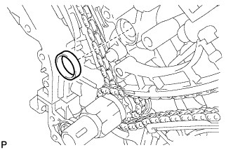 |
Remove the oil pump gasket from the cylinder block.
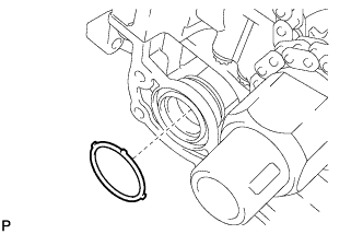 |
Remove the O-ring from the oil pan.
| 43. REMOVE WATER INLET PIPE |
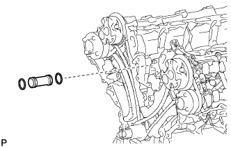 |
Remove the water inlet pipe.
Remove the 2 O-rings from the water inlet pipe.
| 44. REMOVE FRONT CRANKSHAFT OIL SEAL |
Place the timing chain cover on wooden blocks.
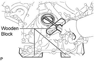 |
Place the oil pump on a wooden block.
Using a screwdriver and wooden block, pry out the oil seal.