CRUISE CONTROL DYNAMIC LASER CRUISE CONTROL SYSTEM P0575 Cruise Control Input Circuit
DESCRIPTION
This DTC is stored when an internal error is detected in the ECM or an STV signal (active brake booster's internal micro switch signal) error is detected.
| DTC Code | DTC Detection Condition | Trouble Area |
|---|---|---|
| P0575 | When STV signal is input and cruise control continues for 0.4 seconds.
When malfunction STV signal is detected for 0.15 seconds. |
·
ECM ·
VSC system ·
Wire harness or connector |
- HINT:
-
The ECM receives signals from each sensor to control all functions of the cruise control system. When a trouble code is detected, the fail-safe functions until the ignition switch is turned off.
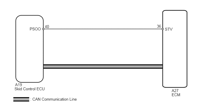
WIRING DIAGRAM
CAUTION / NOTICE / HINT
- HINT:
-
This circuit uses CAN communication. Therefore, Therefore, if there are any malfunctions in the communication circuit, one or more DTCs in the CAN communication system are output.
PROCEDURE
Check for DTCs in Vehicle Stability Control System (See page Brake>BRAKE CONTROL / DYNAMIC CONTROL SYSTEMS>VEHICLE STABILITY CONTROL SYSTEM>DTC CHECK / CLEAR).
| Result | Proceed to |
|---|---|
| DTC is not output | A |
| DTC is out put | B |
A
B
Disconnect the A27 connector from the ECM.
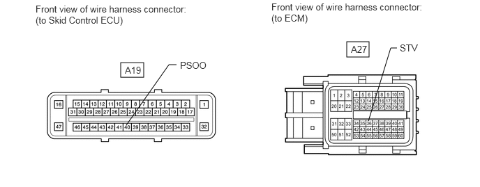
Disconnect the A19 connector the ECU.
Measure the resistance according to the value(s) in the table below.
- Standard Resistance:
Tester Connection Condition Specified Condition A19-40 (PSOO) - A27-36 (STV) Always Below 1 Ω A19-40 (PSOO) or A27-36 (STV) - Body ground Always 10 kΩ or higher
Reconnect the ECM and ECU connector.
| Result | Proceed to |
|---|---|
| NG | A |
| OK (for 3UR-FE) | B |
| OK (for 3UR-FBE) | C |
A
B
C