SUSPENSION CONTROL AIR SUSPENSION SYSTEM C1746 Gate Solenoid Valve Circuit Malfunction
DESCRIPTION
The suspension control ECU opens the gate solenoid valve (No. 2 height control valve) to lead the compressed air to the height control cylinder (pneumatic cylinder) and to raise the vehicle height.
Further, the gate solenoid valve (No. 2 height control valve) opens and closes the passage between the right and left height control cylinders (pneumatic cylinders).
The No. 2 height control valve consists of a leveling solenoid valve and a gate solenoid valve.
The gate solenoid valve opens and closes the passage between the compressor and the height control cylinder (pneumatic cylinder).
| DTC Code | Detection Condition | Trouble Area |
|---|---|---|
| C1746 | When either of the following is detected:
·
With the height control valve inactivated, an open signal of the height control valve is detected for 1 second or more. ·
With the height control valve activated, a short signal of the valve is detected 8 times successively. |
·
Wire harness or connector ·
Gate solenoid valve (No. 2 height control valve) ·
Suspension control ECU |
- HINT:
- ·
Once the ECU stores DTC C1746 in the memory, the vehicle height control is suspended until a normal signal is input to the ECU from the height control solenoid valves. However, control is resumed if the ignition switch is turned off, then to ON again.
·Malfunction in the gate solenoid valve:
The height control operation is suspended, and the height control indicator light does not change by operating the height control switch.
WIRING DIAGRAM
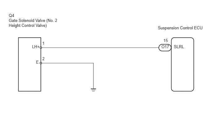
CAUTION / NOTICE / HINT
- NOTICE:
-
After replacing the suspension control ECU, perform registration (See page Suspension>SUSPENSION CONTROL>AIR SUSPENSION SYSTEM>REGISTRATION).
- HINT:
- ·
If DTC C1781 (ECU malfunction) and/or C1782 (power source circuit) is displayed, perform the inspection necessary for DTC C1781 (See page Suspension>SUSPENSION CONTROL>AIR SUSPENSION SYSTEM>C1781) and/or C1782 (See page Suspension>SUSPENSION CONTROL>AIR SUSPENSION SYSTEM>C1782) first.
·If DTC C1781 and the C1782 are output at the same time, perform the inspection necessary for DTC C1782 first.
PROCEDURE
Connect the Techstream to the DLC3.
Turn the ignition switch to ON, and turn the Techstream main switch on.
Enter the following menus: Chassis / Air suspension / Active Test.
| Tester Display | Test Part | Control Range | Diagnostic Note |
|---|---|---|---|
| Rear Gate Solenoid | Gate solenoid valve/ | ON or OFF | Operation sound of solenoid (clicking sound) can be heard |
- OK:
Operation of solenoid (clicking sound) can be heard
| Result | Proceed to |
|---|---|
| NG | A |
| OK (When troubleshooting according to the Problem Symptoms Table) | B |
| OK (When troubleshooting according to the DTC Chart) | C |
A
B
C
(See pageGeneral>INTRODUCTION>HOW TO TROUBLESHOOT ECU CONTROLLED SYSTEMS>HOW TO PROCEED WITH TROUBLESHOOTING)
Turn the ignition switch off.
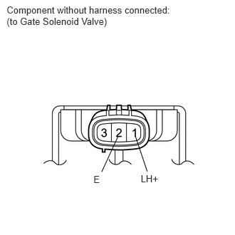
Disconnect Q4 solenoid valve connector.
Measure the resistance according to the value(s) in the table below.
- Standard Resistance:
Tester Connection Condition Specified Condition 1 (LH+) - 2 (E) 20°C (68°F) 17.5 to 21.5 Ω
Connect the battery positive (+) lead to terminal 1 (LH+) and the negative (-) lead to terminal 2 (E) of the solenoid valve connector. Then check that the valve makes an operating sound.
- OK:
Operation of solenoid (clicking sound) can be heard
OK
NG
Disconnect the O17 ECU connector.
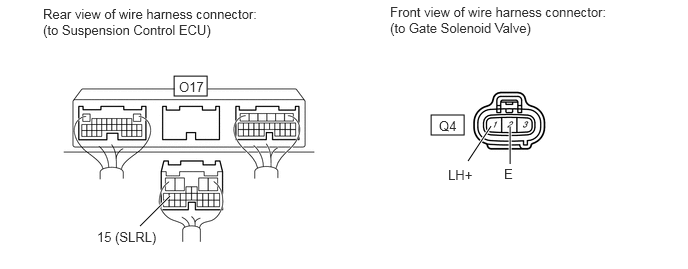
Measure the resistance according to the value(s) in the table below.
- Standard Resistance:
Tester Connection Condition Specified Condition Q4-1 (LH+) - O17-15 (SLRL) Always Below 1 Ω Q4-1 (LH+) or O17-15 (SLRL) - Body ground Always 10 kΩ or higher Q4-2 (E) - Body ground Always Below 1 Ω
OK
NG