BRAKE CONTROL / DYNAMIC CONTROL SYSTEMS VEHICLE STABILITY CONTROL SYSTEM ABS Warning Light Remains ON
DESCRIPTION
If any of the following conditions are detected, the ABS warning light remains on:
The ECU connector is disconnected from the skid control ECU.
There is a malfunction in the skid control ECU internal circuit.
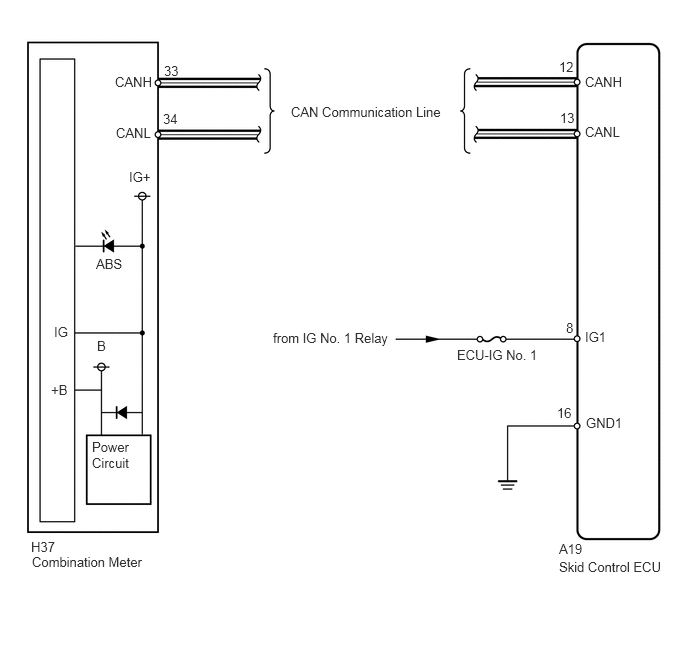
There is an open or short in the CAN communication line between the combination meter and the skid control ECU.
- HINT:
-
The Techstream cannot be used when there is a malfunction in the skid control ECU.
WIRING DIAGRAM
CAUTION / NOTICE / HINT
- NOTICE:
- ·
When replacing the VSC actuator assembly, perform zero point calibration (See page Brake>BRAKE CONTROL / DYNAMIC CONTROL SYSTEMS>VEHICLE STABILITY CONTROL SYSTEM>CALIBRATION).
·Make sure the skid control ECU is not in test mode before proceeding.
·Before using these procedures, first check other DTCs which may cause the ABS warning light to remain on.
PROCEDURE
Check if the CAN communication system DTC is output (See page Power Source / Network>NETWORKING>CAN COMMUNICATION SYSTEM>DIAGNOSIS SYSTEM).
| Result | Proceed to |
|---|---|
| DTC is not output | A |
| DTC is output | B |
A
B
(See pagePower Source / Network>NETWORKING>CAN COMMUNICATION SYSTEM>HOW TO PROCEED WITH TROUBLESHOOTING)
Check the skid control ECU connector condition.
- OK:
The connector is securely connected.
OK
NG
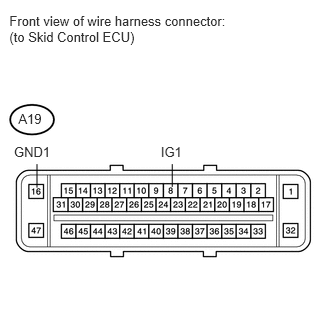
Disconnect the A19 ECU connector.
Turn the ignition switch to ON.
Measure the voltage according to the value(s) in the table below.
- Standard Voltage:
Tester Connection Switch Condition Specified Condition A19-8 (IG1) - A19-16 (GND1) Ignition switch ON 11 to 14 V
Measure the resistance according to the value(s) in the table below.
- Standard Resistance:
Tester Connection Condition Specified Condition A19-16 (GND1) - Body ground Always Below 1 Ω
OK
NG
Connect the Techstream to the DLC3.
Turn the ignition switch to ON.
Turn the Techstream ON.
Select Active Test mode and operate the ABS warning light using the Techstream.
| Tester Display | Test Part | Control Range | Diagnostic Note |
|---|---|---|---|
| ABS Warning Light | ABS warning light | Warning light ON/OFF | Observe combination meter |
Check that the ABS warning light turns on and off in the combination meter when using the Techstream.
- OK:
The ABS warning light turns ON and OFF in accordance with the Techstream operation.
- HINT:
-
When the ABS warning light remains illuminated, an open in the wire harness of the combination meter or abnormalities in the meter circuit should be considered.
OK
NG
(See pageVehicle Interior>METER / GAUGE / DISPLAY>METER / GAUGE SYSTEM>HOW TO PROCEED WITH TROUBLESHOOTING)