Home › Brake › BRAKE CONTROL / DYNAMIC CONTROL SYSTEMS › VEHICLE STABILITY CONTROL SYSTEM
RM27L0U _54 Brake _049321 BRAKE CONTROL / DYNAMIC CONTROL SYSTEMS _0235735 VEHICLE STABILITY CONTROL SYSTEM J

BRAKE CONTROL / DYNAMIC CONTROL SYSTEMS  VEHICLE STABILITY CONTROL SYSTEM  TC and CG Terminal Circuit  


DESCRIPTION

Connecting terminals TC and CG of the DLC3 causes the ECU to display DTCs by blinking the ABS warning light and slip indicator light.

WIRING DIAGRAM
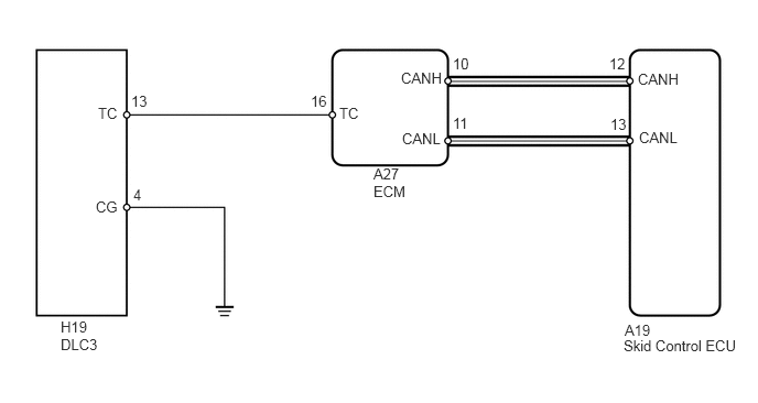
C162042E07
5.906,3.042 6.365,3.198 0.458,0.156 10 false A19 6.031,0.667 6.479,0.865 0.448,0.198 10 false CANH 6.042,1.219 6.448,1.427 0.406,0.208 10 false CANL 3.792,0.656 4.208,0.854 0.417,0.198 10 false CANH 3.802,1.229 4.229,1.438 0.427,0.208 10 false CANL 1.26,1.76 1.375,1.969 0.115,0.208 10 false 4 2.938,0.875 3.125,1.083 0.188,0.208 10 false 16 5.76,0.521 5.948,0.719 0.188,0.198 10 false 12 5.771,1.094 5.948,1.292 0.177,0.198 10 false 13 1.24,0.875 1.458,1.073 0.219,0.198 10 false 13 4.281,0.521 4.49,0.729 0.208,0.208 10 false 10 4.281,1.083 4.49,1.281 0.208,0.198 10 false 11 3.531,1.563 3.927,1.917 0.396,0.354 10 false A27 ECM 0.927,0.99 1.156,1.188 0.229,0.198 10 false TC 0.906,1.875 1.167,2.073 0.26,0.198 10 false CG 3.208,0.99 3.448,1.188 0.24,0.198 10 false TC 0.573,3.01 0.99,3.323 0.417,0.313 10 false H19 DLC3 5.896,3.188 7.083,3.385 1.188,0.198 10 false Skid Control ECU

CAUTION / NOTICE / HINT

NOTICE:
·

When replacing the VSC actuator assembly, perform zero point calibration (See page Brake>BRAKE CONTROL / DYNAMIC CONTROL SYSTEMS>VEHICLE STABILITY CONTROL SYSTEM>CALIBRATION).

·

for 3UR-FE:

If the ECM has been replaced, it is necessary to register the Vehicle Identification Number (VIN) (See page Engine / Hybrid System>3UR-FE ENGINE CONTROL>SFI SYSTEM>REGISTRATION).

·

for 3UR-FBE:

If the ECM has been replaced, it is necessary to register the Vehicle Identification Number (VIN) (See page Engine / Hybrid System>3UR-FBE ENGINE CONTROL>SFI SYSTEM>REGISTRATION).


PROCEDURE
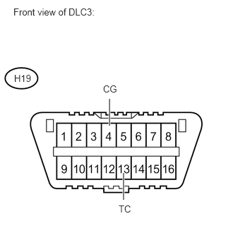
1.INSPECT DLC3 (TC AND CG TERMINAL)
a.
U153425E02
1.615,1.854 1.615,1.458 true 1.823,2.948 1.823,2.552 true 0.198,0.094 1.469,0.26 1.271,0.167 10 false Front view of DLC3: 1.521,1.229 1.76,1.396 0.24,0.167 10 false CG 0.208,1.073 0.479,1.229 0.271,0.156 10 false H19 1.75,3 1.969,3.167 0.219,0.167 10 false TC

Turn the ignition switch to ON.


b.

Measure the voltage according to the value(s) in the table below.

Standard Voltage:
Tester Connection Switch Condition Specified Condition
H19-13 (TC) - Body ground Ignition switch ON 11 to 14 V


c.

Measure the resistance according to the value(s) in the table below.

Standard Resistance:
Tester Connection Condition Specified Condition
H19-4 (CG) - Body ground Always Below 1 Ω


OK

2.CHECK CAN COMMUNICATION SYSTEM

NG

3.CHECK HARNESS AND CONNECTOR (DLC3 - ECM)
2.CHECK CAN COMMUNICATION SYSTEM
a.

Check if the CAN communication DTC is output (See page Power Source / Network>NETWORKING>CAN COMMUNICATION SYSTEM>DIAGNOSIS SYSTEM).

Result
Result Proceed to
DTC is not output A
DTC is output B


A

3.CHECK HARNESS AND CONNECTOR (DLC3 - ECM)

B

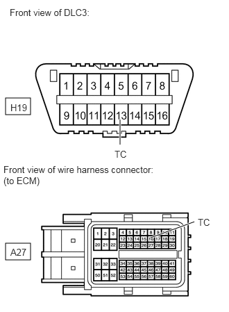
3.CHECK HARNESS AND CONNECTOR (DLC3 - ECM)
C353404E01
0.083,1.469 0.458,1.719 0.375,0.25 0.083,3.646 0.458,3.896 0.375,0.25 1.802,2.167 1.802,1.792 true 2.26,3.563 2.917,3.323 true 0.146,0.104 3.052,0.302 2.906,0.198 10 false Front view of DLC3: 0.156,1.531 0.656,1.74 0.5,0.208 10 false H19 1.719,2.229 2.156,2.448 0.438,0.219 10 false TC 0.052,2.458 2.365,2.792 2.313,0.333 10 false Front view of wire harness connector: (to ECM) 0.156,3.698 0.656,3.906 0.5,0.208 10 false A27 2.969,3.25 3.198,3.406 0.229,0.156 10 false TC

a.

Disconnect the A27 ECM connector.


b.

Measure the resistance according to the value(s) in the table below.

Standard Resistance:
Tester Connection Condition Specified Condition
H19-13 (TC) - A27-16 (TC) Always Below 1 Ω
H19-13 (TC) - Body ground Always 10 kΩ or higher


OK

4.CHECK HARNESS AND CONNECTOR (DLC3 - BODY GROUND)

NG

REPAIR OR REPLACE HARNESS OR CONNECTOR

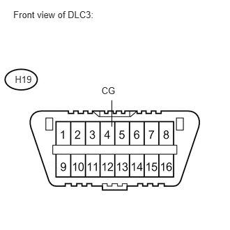
4.CHECK HARNESS AND CONNECTOR (DLC3 - BODY GROUND)
a.
U153426E01
0.199,0.135 1.469,0.304 1.269,0.170 10 Front view of DLC3: 1.517,1.269 1.756,1.439 0.239,0.170 10 CG 0.223,1.104 0.555,1.262 0.332,0.158 10 H19 1.672,1.893 1.672,1.498 false

Measure the resistance according to the value(s) in the table below.

Standard Resistance:
Tester Connection Condition Specified Condition
H19-4 (CG) - Body ground Always Below 1 Ω


OK

5.INSPECT ECM (DLC3 INPUT)

NG

REPAIR OR REPLACE HARNESS OR CONNECTOR

5.INSPECT ECM (DLC3 INPUT)
a.
U153425E02
1.615,1.854 1.615,1.458 true 1.823,2.948 1.823,2.552 true 0.198,0.094 1.469,0.26 1.271,0.167 10 false Front view of DLC3: 1.521,1.229 1.76,1.396 0.24,0.167 10 false CG 0.208,1.073 0.479,1.229 0.271,0.156 10 false H19 1.75,3 1.969,3.167 0.219,0.167 10 false TC

Using SST, connect terminals 13 (TC) and 4 (CG) of the DLC3.


SST
09843-18040  

b.

Check if the ABS warning light is blinking.

Result
Result Proceed to
ABS warning light is blinking A
ABS warning light is not blinking (for 3UR-FE) B
ABS warning light is not blinking (for 3UR-FBE) C


A

B

C