Home › Brake › BRAKE CONTROL / DYNAMIC CONTROL SYSTEMS › VEHICLE STABILITY CONTROL SYSTEM
RM27L0U _54 Brake _049321 BRAKE CONTROL / DYNAMIC CONTROL SYSTEMS _0235735 VEHICLE STABILITY CONTROL SYSTEM J

BRAKE CONTROL / DYNAMIC CONTROL SYSTEMS  VEHICLE STABILITY CONTROL SYSTEM  AUTO LSD Indicator Light Remains ON  


DESCRIPTION

For 2WD vehicles and 4WD vehicles in H2 mode, if the VSC OFF switch is pressed for a short amount of time (approximately 1 second), or if the vehicle is stopped and the VSC OFF switch is pressed for 3 seconds or more, the AUTO LSD function is activated and the AUTO LSD indicator light illuminates.

WIRING DIAGRAM
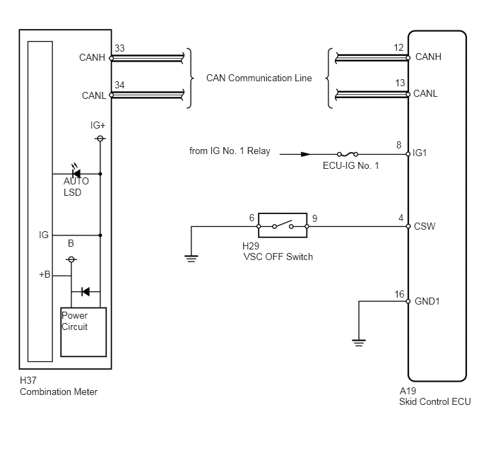
C244863E08
0.573,3.375 0.813,3.573 0.24,0.198 10 false IG 0.906,4.563 1.521,4.938 0.615,0.375 10 false Power Circuit 0.938,2.583 1.365,2.906 0.427,0.323 10 false AUTO LSD 1.333,1.76 1.615,1.948 0.281,0.188 10 false IG+ 1.688,0.625 1.969,0.813 0.281,0.188 10 false 33 1.688,1.167 1.969,1.354 0.281,0.188 10 false 34 4.76,2.354 5.698,2.542 0.938,0.188 10 false ECU-IG No. 1 3.594,3.698 4.719,3.885 1.125,0.188 10 false VSC OFF Switch 6.083,2.167 6.354,2.354 0.271,0.188 10 false IG1 6.094,1.292 6.573,1.479 0.479,0.188 10 false CANL 6.104,3.25 6.583,3.438 0.479,0.188 10 false CSW 6.125,0.75 6.604,0.938 0.479,0.188 10 false CANH 5.844,2.052 5.938,2.24 0.094,0.188 10 false 8 5.875,3.125 5.979,3.313 0.104,0.188 10 false 4 3.677,3.125 3.906,3.313 0.229,0.188 10 false 6 4.604,3.135 4.833,3.323 0.229,0.188 10 false 9 5.823,1.135 6,1.323 0.177,0.188 10 false 13 5.802,0.615 5.979,0.802 0.177,0.188 10 false 12 5.813,4.25 5.99,4.438 0.177,0.188 10 false 16 6.115,4.354 6.563,4.542 0.448,0.188 10 false GND1 2.792,2.135 4.198,2.323 1.406,0.188 10 false from IG No. 1 Relay 3.042,1.063 4.708,1.25 1.667,0.188 10 false CAN Communication Line 0.292,5.521 0.656,5.708 0.365,0.188 10 false H37 0.292,5.688 1.677,5.896 1.385,0.208 10 false Combination Meter 5.896,5.677 6.26,5.865 0.365,0.188 10 false A19 5.885,5.833 7.031,6.042 1.146,0.208 10 false Skid Control ECU 3.573,3.542 3.938,3.729 0.365,0.188 10 false H29 1.208,1.323 1.625,1.51 0.417,0.188 10 false CANL 1.167,0.76 1.583,0.948 0.417,0.188 10 false CANH 0.573,3.958 0.854,4.156 0.281,0.198 10 false +B 1,3.5 1.281,3.698 0.281,0.198 10 false B

CAUTION / NOTICE / HINT

NOTICE:

When replacing the VSC actuator assembly, perform zero point calibration (See page Brake>BRAKE CONTROL / DYNAMIC CONTROL SYSTEMS>VEHICLE STABILITY CONTROL SYSTEM>CALIBRATION).


PROCEDURE

1.CHECK CAN COMMUNICATION SYSTEM
a.

Check if a CAN communication system DTC is output (See page Power Source / Network>NETWORKING>CAN COMMUNICATION SYSTEM>DIAGNOSIS SYSTEM).

Result
Result Proceed to
DTC is not output A
DTC is output B


A

2.PERFORM ACTIVE TEST USING TECHSTREAM (AUTO LSD INDICATOR LIGHT)

B

2.PERFORM ACTIVE TEST USING TECHSTREAM (AUTO LSD INDICATOR LIGHT)
a.

Connect the Techstream to the DLC3.


b.

Turn the ignition switch to ON.


c.

Turn the Techstream ON.


d.

Select the Active Test mode and operate the AUTO LSD indicator light using the Techstream.

ABS/VSC/TRAC
Tester Display Test Part Control Range Diagnostic Note
Auto LSD Indicator Light AUTO LSD indicator light Indicator light ON/OFF Observe combination meter


e.

Check that the AUTO LSD indicator light turns ON and OFF in the combination meter when using the Techstream.

OK:

The AUTO LSD indicator light turns on and off in accordance with the Techstream operation.


HINT:

When the AUTO LSD indicator light remains illuminated, there may be an open in the wire harness of the combination meter or abnormalities in the meter circuit.


OK

3.INSPECT VSC OFF SWITCH

NG

3.INSPECT VSC OFF SWITCH
a.
C179171E02
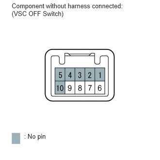
0.25,0.044 2.740,0.520 2.489,0.476 10 Component without harness connected: (VSC OFF Switch) 0.517,2.848 1.183,3.021 0.666,0.174 10 : No pin

Remove the VSC OFF switch (See page Brake>BRAKE CONTROL / DYNAMIC CONTROL SYSTEMS>VSC OFF SWITCH>REMOVAL).


b.

Measure the resistance according to the value(s) in the table below.

Standard Resistance:
Tester Connection Switch Condition Specified Condition
6 - 9 Switch is pressed Below 1 Ω
Switch is not pressed 10 kΩ or higher


OK

4.CHECK HARNESS AND CONNECTOR (SKID CONTROL ECU - VSC OFF SWITCH)

NG

4.CHECK HARNESS AND CONNECTOR (SKID CONTROL ECU - VSC OFF SWITCH)
a.
U153719E02
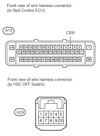
2.417,1.573 2.417,1.25 true 0.24,0.104 2.51,0.417 2.271,0.313 10 false Front view of wire harness connector: (to Skid Control ECU) 0.177,0.958 0.448,1.135 0.271,0.177 10 false A19 2.26,1.042 2.625,1.188 0.365,0.146 10 false CSW 0.26,2.646 2.521,2.969 2.26,0.323 10 false Front view of wire harness connector: (to VSC OFF Switch) 0.573,3.781 0.865,3.958 0.292,0.177 10 false H29

Disconnect the A19 ECU connector.


b.

Disconnect the H29 switch connector.


c.

Measure the resistance according to the value(s) in the table below.

Standard Resistance:
Tester Connection Condition Specified Condition
A19-4 (CSW) - H29-9 Always Below 1 Ω
A19-4 (CSW) - Body ground Always 10 kΩ or higher


OK

NG

REPAIR OR REPLACE HARNESS OR CONNECTOR