Home › Power Source / Network › NETWORKING › CAN COMMUNICATION SYSTEM
RM27L0U _57 Power Source / Network _049335 NETWORKING _0235802 CAN COMMUNICATION SYSTEM C

NETWORKING  CAN COMMUNICATION SYSTEM  B2621  Communication Interruption  


DESCRIPTION

The multiplex tilt and telescopic ECU forms a network with the ECUs of other systems through the CAN communication bus, each ECU informs the other ECUs that it is connected to the network by outputting a specified signal (periodic signal) onto the CAN communication bus on a regular schedule. The multiplex tilt and telescopic ECU detects the connection of each ECU based on the signal.

DTC Code DTC Detection Condition Trouble Area
B2621 Periodic signal from the specified ECU has stopped.
·

MS bus circuit

·

Multiplex tilt and telescopic ECU CAN branch wire or connector

·

Main body ECU (cowl side junction block LH) CAN main wire or connector

·

Multiplex tilt and telescopic ECU

·

Main body ECU (cowl side junction block LH)


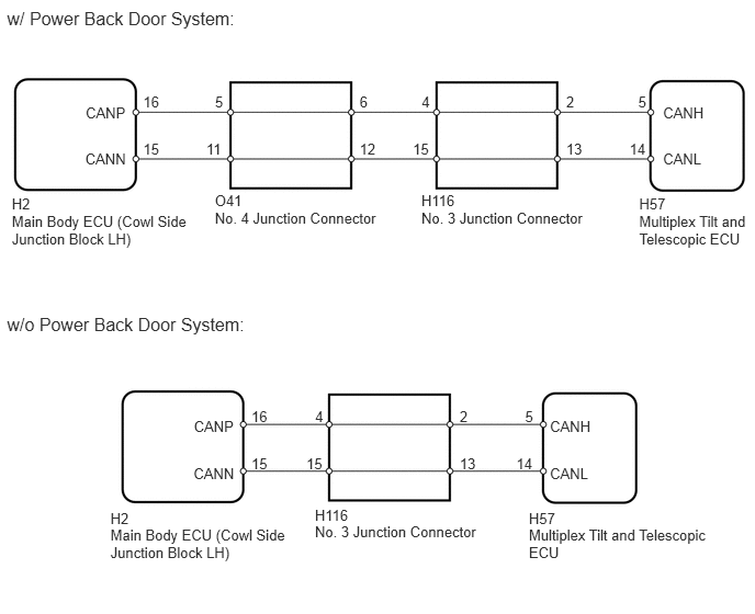
WIRING DIAGRAM

C244508E02
0.112,1.855 1.858,2.178 1.746,0.323 10 H2 0.112,2.016 1.858,2.339 1.746,0.323 10 Main Body ECU (Cowl Side Junction Block LH) 6.067,1.855 7.129,2.178 1.062,0.323 10 H57 6.067,2.016 7.129,2.339 1.062,0.323 10 Multiplex Tilt and Telescopic ECU 4,1.824 5.062,2.146 1.062,0.323 10 H116 4,1.985 5.642,2.127 1.642,0.142 10 No. 3 Junction Connector 2.039,1.824 3.101,2.146 1.062,0.323 10 O41 2.039,1.985 3.681,2.127 1.642,0.142 10 No. 4 Junction Connector 0.813,0.987 1.222,1.125 0.409,0.139 10 CANP 0.809,1.431 1.222,1.570 0.413,0.139 10 CANN 6.294,0.987 6.710,1.125 0.416,0.139 10 CANH 6.294,1.431 6.707,1.570 0.413,0.139 10 CANL 1.359,0.888 1.538,1.027 0.179,0.139 10 16 1.359,1.333 1.539,1.472 0.180,0.139 10 15 2.041,0.888 2.139,1.027 0.098,0.139 10 5 1.958,1.333 2.138,1.472 0.180,0.139 10 11 3.413,0.888 3.510,1.027 0.098,0.139 10 6 3.413,1.333 3.593,1.472 0.180,0.139 10 12 4.002,0.888 4.100,1.027 0.098,0.139 10 4 3.919,1.333 4.100,1.472 0.180,0.139 10 15 5.374,0.888 5.472,1.027 0.098,0.139 10 2 5.374,1.333 5.554,1.472 0.180,0.139 10 13 6.058,0.888 6.156,1.027 0.098,0.139 10 5 5.975,1.333 6.156,1.472 0.180,0.139 10 14 1.048,4.842 2.795,5.164 1.746,0.323 10 H2 1.048,5.003 2.795,5.325 1.746,0.323 10 Main Body ECU (Cowl Side Junction Block LH) 5.02,4.842 6.083,5.164 1.062,0.323 10 H57 5.02,5.003 6.777,5.325 1.757,0.323 10 Multiplex Tilt and Telescopic ECU 2.989,4.81 4.051,5.133 1.062,0.323 10 H116 2.989,4.971 4.631,5.113 1.642,0.142 10 No. 3 Junction Connector 1.84,3.973 2.249,4.112 0.409,0.139 10 CANP 1.837,4.418 2.249,4.556 0.413,0.139 10 CANN 5.22,3.973 5.636,4.112 0.416,0.139 10 CANH 5.22,4.418 5.633,4.556 0.413,0.139 10 CANL 2.386,3.875 2.565,4.014 0.179,0.139 10 16 2.386,4.32 2.567,4.458 0.180,0.139 10 15 2.991,3.875 3.089,4.014 0.098,0.139 10 4 2.908,4.32 3.089,4.458 0.180,0.139 10 15 4.363,3.875 4.461,4.014 0.098,0.139 10 2 4.363,4.32 4.543,4.458 0.180,0.139 10 13 4.984,3.875 5.082,4.014 0.098,0.139 10 5 4.901,4.32 5.082,4.458 0.180,0.139 10 14 0.067,0.077 2.288,0.255 2.222,0.178 12 w/ Power Back Door System: 0.067,2.982 2.362,3.160 2.296,0.178 12 w/o Power Back Door System:

PROCEDURE

1.CHECK FOR DTC
a.

Check for DTCs (See page Power Source / Network>NETWORKING>CAN COMMUNICATION SYSTEM>DIAGNOSIS SYSTEM).

Result
Result Proceed to
DTC B2621 is output alone A
DTC B2621 and U1115 and/or U1002 are output B

HINT:

When DTC B2621 and U1115 and/or U1002 are output simultaneously, perform the troubleshooting for DTC U1115 and/or U1002 first.


A

B