Home › Vehicle Interior › DOOR LOCK › POWER DOOR LOCK CONTROL SYSTEM
RM27L0U _58 Vehicle Interior _049336 DOOR LOCK _0235814 POWER DOOR LOCK CONTROL SYSTEM J

DOOR LOCK  POWER DOOR LOCK CONTROL SYSTEM  All Doors cannot be Locked / Unlocked Simultaneously  


DESCRIPTION

The main body ECU receives switch signals from the power window regulator master switch, switch signal from the front door lock switch, tail gate control switch signal and driver side door key cylinder switch signals from the front door look. The main body ECU activates the door look motor on each door according to the signals.

HINT:

Since the power door lock control system has functions that use LIN communication, first confirm that there is no malfunction in the communication system by inspecting the LIN communication functions in accordance with the "How to Proceed with Troubleshooting" procedures. Then, conduct the following inspection procedure.


WIRING DIAGRAM
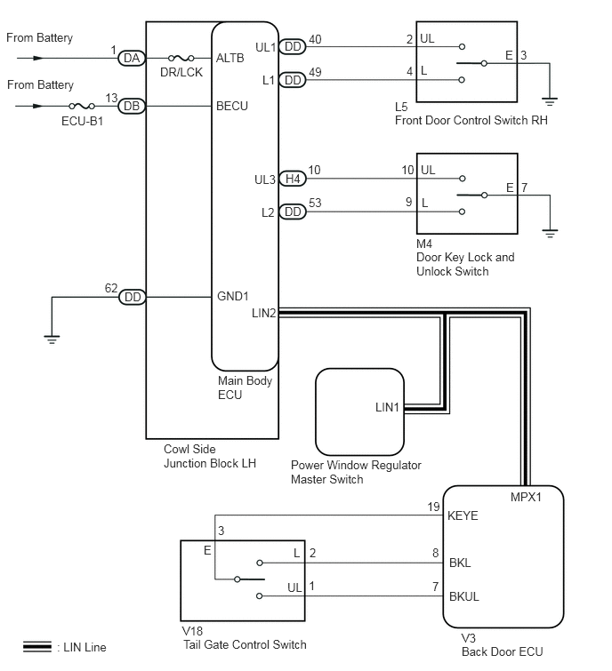
B189773E04
0.083,0.906 0.906,1.115 0.823,0.208 10 false From Battery 0.719,1.333 1.26,1.479 0.542,0.146 10 false ECU-B1 0.073,0.354 0.906,0.583 0.833,0.229 10 false From Battery 1.448,1.156 1.688,1.302 0.24,0.146 10 false DB 1.448,0.594 1.677,0.74 0.229,0.146 10 false DA 1.292,0.5 1.406,0.646 0.115,0.146 10 false 1 1.229,1.063 1.406,1.208 0.177,0.146 10 false 13 1.875,0.76 2.427,0.917 0.552,0.156 10 false DR/LCK 2.531,0.594 2.896,0.74 0.365,0.146 10 false ALTB 2.531,1.156 2.948,1.302 0.417,0.146 10 false BECU 2.99,0.469 3.271,0.625 0.281,0.156 10 false UL1 3.073,0.854 3.26,1.01 0.188,0.156 10 false L1 3.333,0.854 3.552,1 0.219,0.146 10 false DD 1.458,3.396 1.677,3.542 0.219,0.146 10 false DD 3.333,0.458 3.552,0.604 0.219,0.146 10 false DD 2.542,3.385 3.01,3.552 0.469,0.167 10 false GND1 1.229,3.292 1.406,3.438 0.177,0.146 10 false 62 3.615,0.375 3.792,0.521 0.177,0.146 10 false 40 3.615,0.76 3.813,0.906 0.198,0.146 10 false 49 4.76,0.375 4.865,0.542 0.104,0.167 10 false 2 4.76,0.75 4.875,0.896 0.115,0.146 10 false 4 4.917,0.365 5.125,0.51 0.208,0.146 10 false UL 4.927,0.74 5.052,0.885 0.125,0.146 10 false L 5.917,0.563 6.031,0.708 0.115,0.146 10 false E 6.094,0.563 6.208,0.708 0.115,0.146 10 false 3 4.927,1.906 5.135,2.052 0.208,0.146 10 false UL 3.365,6.802 3.573,6.948 0.208,0.146 10 false UL 4.938,2.292 5.063,2.438 0.125,0.146 10 false L 3.438,6.396 3.563,6.542 0.125,0.146 10 false L 5.927,2.115 6.042,2.26 0.115,0.146 10 false E 2.385,6.365 2.5,6.51 0.115,0.146 10 false E 6.104,2.115 6.208,2.271 0.104,0.156 10 false 7 4.698,1.906 4.875,2.083 0.177,0.177 10 false 10 4.75,2.281 4.854,2.448 0.104,0.167 10 false 9 3.604,1.906 3.781,2.083 0.177,0.177 10 false 10 3.615,2.292 3.792,2.438 0.177,0.146 10 false 53 3.333,2.396 3.552,2.542 0.219,0.146 10 false DD 3.344,2.01 3.542,2.167 0.198,0.156 10 false H4 2.979,2.021 3.26,2.167 0.281,0.146 10 false UL3 3.063,2.406 3.25,2.552 0.188,0.146 10 false L2 2.948,3.583 3.271,3.729 0.323,0.146 10 false LIN2 5.979,5.74 6.406,5.885 0.427,0.146 10 false MPX1 4.396,4.688 4.708,4.833 0.313,0.146 10 false LIN1 5.24,5.958 5.646,6.115 0.406,0.156 10 false KEYE 5.26,6.51 5.573,6.656 0.313,0.146 10 false BKL 5.26,6.906 5.667,7.052 0.406,0.146 10 false BKUL 5,5.854 5.198,6 0.198,0.146 10 false 19 5.063,6.396 5.156,6.542 0.094,0.146 10 false 8 5.063,6.792 5.167,6.948 0.104,0.156 10 false 7 4.625,1.323 6.51,1.49 1.885,0.167 10 false Front Door Control Switch RH 4.625,1.167 4.844,1.333 0.219,0.167 10 false L5 4.875,2.927 6.083,3.25 1.208,0.323 10 false Door Key Lock and Unlock Switch 4.875,2.771 5.115,2.927 0.24,0.156 10 false M4 3.406,5.365 5.01,5.688 1.604,0.323 10 false Power Window Regulator Master Switch 1.917,5.177 3.031,5.542 1.115,0.365 10 false Cowl Side Junction Block LH 2.552,4.375 3.24,4.688 0.688,0.313 10 false Main Body ECU 2.146,7.469 3.698,7.625 1.552,0.156 10 false Tail Gate Control Switch 2.135,7.313 2.427,7.469 0.292,0.156 10 false V18 5.406,7.552 6.427,7.708 1.021,0.156 10 false Back Door ECU 5.406,7.396 5.604,7.552 0.198,0.156 10 false V3 0.667,7.5 1.302,7.646 0.635,0.146 10 false : LIN Line 3.615,6.781 3.729,6.927 0.115,0.146 10 false 1 3.625,6.396 3.729,6.563 0.104,0.167 10 false 2 2.552,6.135 2.667,6.281 0.115,0.146 10 false 3

PROCEDURE

1.CHECK POWER DOOR LOCK OPERATION
a.

Check the power door lock operation.

Result
Result Proceed to
All doors cannot be locked through power window regulator master switch, door control switch RH, tail gate control switch, and driver side door key link switch. A
All doors cannot be locked through power window regulator master switch . B
All doors cannot be locked through tail gate control switch. C
All doors cannot be locked through door control switch RH. D
All doors cannot be locked through driver side door key link switch. E


A

2.INSPECT FUSES (ECU-B1, DR/LCK)

B

4.READ VALUE USING TECHSTREAM

C

5.READ VALUE USING TECHSTREAM (TAIL GATE CONTROL SWITCH OPERATION)

D

9.READ VALUE USING TECHSTREAM (DOOR LOCK SWITCH RH)

E

12.READ VALUE USING TECHSTREAM (DRIVER SIDE LOCK/UNLOCK KEY SWITCH)
2.INSPECT FUSES (ECU-B1, DR/LCK)
a.

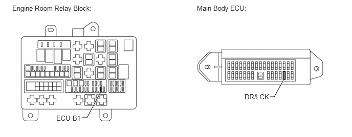
Remove the ECU-B1 and DR/LCK fuses.


B443300E01
1.677,2.406 1.771,2.406 1.771,2.406 2.052,1.875 true 5.5,1.979 5.583,1.979 5.583,1.979 5.771,1.635 true 0.25,0.083 1.927,0.281 1.677,0.198 10 false Engine Room Relay Block: 4.01,0.083 5.688,0.281 1.677,0.198 10 false Main Body ECU: 1.146,2.333 1.677,2.531 0.531,0.198 10 false ECU-B1 4.979,1.896 5.51,2.094 0.531,0.198 10 false DR/LCK

b.

Measure the resistance according to the value(s) in the table below.

Standard Resistance:
Tester Connection Condition Specified Condition
ECU-B1 fuse Always Below 1 Ω
DR/LCK fuse Always Below 1 Ω


c.

Reinstall the ECU-B1 and DR/LCK fuses.


OK

3.CHECK HARNESS AND CONNECTOR (MAIN BODY ECU - BATTERY AND BODY GROUND)

NG

CHECK FOR SHORTS IN ALL HARNESSES AND CONNECTORS CONNECTED TO FUSE AND REPLACE FUSES

3.CHECK HARNESS AND CONNECTOR (MAIN BODY ECU - BATTERY AND BODY GROUND)
a.

Disconnect DA, DB, and DD main body ECU connectors.
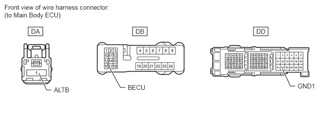

B443301E01
0.604,0.583 0.917,0.771 0.313,0.188 2.844,0.583 3.156,0.771 0.313,0.188 5.438,0.583 5.75,0.771 0.313,0.188 1.104,1.938 1,1.938 1,1.938 0.833,1.573 true 2.688,1.885 2.583,1.885 2.583,1.885 2.281,1.333 true 6.333,1.854 6.229,1.854 6.229,1.854 6.063,1.49 true 0.094,0.073 2.354,0.448 2.26,0.375 10 false Front view of wire harness connector: (to Main Body ECU) 0.667,0.594 0.979,0.792 0.313,0.198 10 false DA 2.906,0.594 3.219,0.792 0.313,0.198 10 false DB 5.5,0.594 5.813,0.792 0.313,0.198 10 false DD 1.156,1.854 1.542,2.063 0.385,0.208 10 false ALTB 6.385,1.771 6.802,1.958 0.417,0.188 10 false GND1 2.74,1.802 3.156,1.99 0.417,0.188 10 false BECU

b.

Measure the voltage and resistance and voltage according to the value(s) in the table below.

Standard Voltage :
Tester Connection Condition Specified Condition
DA-1 (ALTB) - Body ground Always 11 to 14 V
DB-13 (BECU) - Body ground Always 11 to 14 V


Standard Resistance:
Tester Connection Condition Specified Condition
DD-62 (GND1) - Body ground Always Below 1 Ω


c.

Reconnect main body ECU connector.


OK

REPLACE MAIN BODY ECU

NG

REPAIR OR REPLACE HARNESS OR CONNECTOR

4.READ VALUE USING TECHSTREAM
a.

Connect the Techstream to the DLC3.


b.

Turn the ignition switch to ON.


c.

Turn the Techstream on.


d.

Enter the following menus: Body Electrical / Master Switch / Data List.


e.

According to the display on the Techstream, read the "Data List".

Master Switch
Tester Display Measurement Item/Range Normal Condition Diagnostic Note
Door Lock Switch Status Driver door lock switch signal/ ON or OFF ON: Driver door lock switch is turned to LOCK
OFF: ON: Driver door lock switch is not turned
-
Door Unlock Switch Status Driver door unlock switch signal/ ON or OFF ON: Driver door unlock switch is turned to UNLOCK
OFF: ON: Driver door unlock switch is not turned
-

OK:

The display is as specified in the normal condition column.


OK

REPLACE MAIN BODY ECU

NG

REPLACE POWER WINDOW REGULATOR MASTER SWITCH

5.READ VALUE USING TECHSTREAM (TAIL GATE CONTROL SWITCH OPERATION)
a.

Connect the Techstream to the DLC3.


b.

Turn the ignition switch to ON.


c.

Turn the Techstream on.


d.

Enter the following menus: Body Electrical / Back Door P/W / Data List.


e.

According to the display on the Techstream, read the "Data List".

Back Door P/W (Back Door ECU)
Tester Display Measurement Item/Range Normal Condition Diagnostic Note
Key Switch Operation Locked Tail gate control switch signal/ON or OFF ON: Back door key cylinder is turned to LOCK
OFF: Driver side door key cylinder is not turned
-
Key Switch Operation Unlocked Tail gate control switch signal/ON or OFF ON: Back door key cylinder is turned to UNLOCK
OFF: Back door key cylinder is not turned
-

OK:

The display is as specified in the normal condition column.


OK

6.READ VALUE USING TECHSTREAM (BACK DOOR OPEN)

NG

7.CHECK HARNESS AND CONNECTOR (TAIL GATE CONTROL SWITCH - BACK DOOR ECU)
6.READ VALUE USING TECHSTREAM (BACK DOOR OPEN)
a.

Connect the Techstream to the DLC3.


b.

Turn the ignition switch to ON.


c.

Turn the Techstream on.


d.

Enter the following menus: Body Electrical / Main Body / Data List.


e.

According to the display on the Techstream, read the "Data List".

Main Body (Main Body ECU)
Tester Display Measurement Item/Range Normal Condition Diagnostic Note
Back Door Open Back door lock signal/Permit or Prohibit Permit: Back door is UNLOCK
Prohibit: Back door is LOCK
-

OK:

The display is as specified in the normal condition column.


OK

REPLACE MAIN BODY ECU

NG

REPLACE BACK DOOR ECU

7.CHECK HARNESS AND CONNECTOR (TAIL GATE CONTROL SWITCH - BACK DOOR ECU)
a.

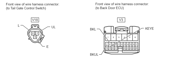
Disconnect V18 switch connector.


B443302E01
1.313,0.75 1.635,0.938 0.323,0.188 4.948,0.75 5.271,0.938 0.323,0.188 0.865,1.073 0.958,1.073 0.958,1.073 1.344,1.375 true 1.51,1.594 1.792,1.969 1.792,1.969 1.896,1.969 true 1.604,1.385 2.01,1.135 2.01,1.135 2.115,1.135 true 4.083,1.229 4.198,1.229 4.198,1.229 4.635,1.823 true 4.635,1.99 5.979,1.198 5.979,1.198 6.063,1.198 true 4.177,2.313 4.271,2.313 4.271,2.313 4.51,1.906 true 0.25,0.094 2.542,0.458 2.292,0.365 10 false Front view of wire harness connector: (to Tail Gate Control Switch) 4.021,0.083 6.313,0.448 2.292,0.365 10 false Front view of wire harness connector: (to Back Door ECU) 1.354,0.76 1.667,0.927 0.313,0.167 10 false V18 5.021,0.76 5.25,0.927 0.229,0.167 10 false V3 6.125,1.125 6.563,1.302 0.438,0.177 10 false KEYE 3.792,2.229 4.229,2.406 0.438,0.177 10 false BKUL 3.792,1.156 4.135,1.333 0.344,0.177 10 false BKL 2.167,1.063 2.51,1.24 0.344,0.177 10 false UL 0.75,1 0.958,1.167 0.208,0.167 10 false L 1.958,1.896 2.167,2.063 0.208,0.167 10 false E

b.

Disconnect V3 ECU connector.


c.

Measure the resistance according to the value(s) in the table below.

Standard Resistance:
Tester Connection Condition Specified Condition
V18-1 (UL) - V3-7 (BKUL) Always Below 1 Ω
V18-2 (L) - V3-8 (BKL) Always Below 1 Ω
V18-3 (E) - V3-19 (KEYE) Always Below 1 Ω
V18-1 (UL) or V3-7 (BKUL) - Body ground Always 10 kΩ or higher
V18-2 (L) or V3-8 (BKL) - Body ground Always 10 kΩ or higher


d.

Reconnect the switch and ECU connector.


OK

8.INSPECT TAIL GATE CONTROL SWITCH

NG

REPAIR OR REPLACE HARNESS OR CONNECTOR

8.INSPECT TAIL GATE CONTROL SWITCH
a.

Remove the tail gate control switch (See page Vehicle Exterior>DOOR / HATCH>BACK DOOR>DISASSEMBLY).
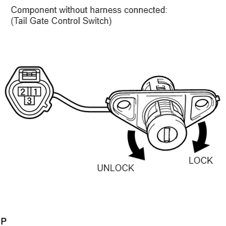

B189798E01
2.868,2.353 3.290,2.513 0.422,0.160 10 LOCK 1.474,2.474 2.105,2.647 0.630,0.173 10 UNLOCK 0.162,0.066 2.671,0.420 2.509,0.354 10 Component without harness connected: (Tail Gate Control Switch)

b.

Measure the resistance according to the value(s) in the table below.

Standard Resistance:
Tester Connection Switch Condition Specified Condition
1 (UL) - 3 (E) Lock position Below 1 Ω
2 (L) - 3 (E) Unlock position Below 1 Ω
2 (L) - 3 (E) Lock position 10 kΩ or higher
1 (UL) - 3 (E) Unlock position 10 kΩ or higher


c.

Reinstall the tail gate control switch.


OK

REPLACE BACK DOOR ECU

NG

REPLACE TAIL GATE CONTROL SWITCH

9.READ VALUE USING TECHSTREAM (DOOR LOCK SWITCH RH)
a.

Connect the Techstream to the DLC3.


b.

Turn the ignition switch to ON.


c.

Turn the Techstream on.


d.

Enter the following menus: Body Electrical / Main Body / Data List.


e.

According to the display on the Techstream, read the "Data List".

Main Body
Tester Display Measurement Item/Range Normal Condition Diagnostic Note
Door Lock SW-Lock Door manual lock switch signal ON or OFF ON: Door control switch is pushed to lock position
OFF: Door control switch is not pushed
-
Door Lock SW-Unlock Door manual unlock switch signal / ON or OFF ON: Door control switch is pushed to unlock position
OFF: Door control switch is not pushed
-

OK:

The display is as specified in the normal condition column.


OK

REPLACE MAIN BODY ECU

NG

10.CHECK HARNESS AND CONNECTOR (FRONT DOOR CONTROL SWITCH - MAIN BODY ECU)
a.

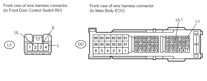
Disconnect the L5 switch connector.


E147842E04
6.49,1.281 6.792,0.833 false 6.063,1.417 6.177,0.771 false 1.188,1.573 0.698,1.156 false 1.635,1.573 1.927,1.573 false 1.417,1.563 1.792,1.052 false 0.49,1.042 0.688,1.219 0.198,0.177 10 false UL 1.802,0.885 1.958,1.063 0.156,0.177 10 false E 1.979,1.49 2.135,1.667 0.156,0.177 10 false L 6.771,0.656 6.938,0.833 0.167,0.177 10 false L1 6.083,0.604 6.354,0.781 0.271,0.177 10 false UL1 0.115,0.104 2.469,0.469 2.354,0.365 10 false Front view of wire harness connector: (to Front Door Control Switch RH) 3.104,0.115 5.469,0.479 2.365,0.365 10 false Front view of wire harness connector: (to Main Body ECU) 2.698,1.448 2.927,1.604 0.229,0.156 10 false DD 0.25,1.469 0.427,1.615 0.177,0.146 10 false L5

b.

Disconnect the DD ECU connector.


c.

Measure the resistance according to the value(s) in the table below.

Standard Resistance:
Tester Connection Condition Specified Condition
L5-4 (L) - DD-49 (L1) Always Below 1 Ω
L5-2 (UL) - DD-40 (UL1) Always Below 1 Ω
L5-3 (E) - Body ground Always Below 1 Ω
DD-49 (L1) - Body ground Always 10 kΩ or higher
DD-40 (UL1) - Body ground Always 10 kΩ or higher


d.

Reconnect the switch and ECU connector.


OK

11.INSPECT DOOR CONTROL SWITCH RH

NG

REPAIR OR REPLACE HARNESS OR CONNECTOR

11.INSPECT DOOR CONTROL SWITCH RH
a.

Remove the door control switch (See page Vehicle Interior>DOOR LOCK>FRONT DOOR LOCK>REMOVAL).
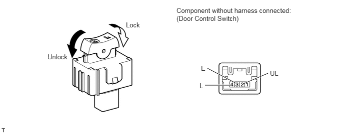

B443303E01
4.271,1.781 4.802,1.781 true 4.323,1.427 4.917,1.74 true 5.073,1.75 5.583,1.531 true 2.625,0.438 3.24,0.635 0.615,0.198 10 false Lock 0.99,1.104 1.604,1.302 0.615,0.198 10 false Unlock 3.677,0.135 6.177,0.49 2.5,0.354 10 false Component without harness connected: (Door Control Switch) 5.625,1.448 5.938,1.646 0.313,0.198 10 false UL 4.156,1.708 4.313,1.906 0.156,0.198 10 false L 4.188,1.344 4.344,1.51 0.156,0.167 10 false E

b.

Measure the resistance according to the value(s) in the table below.

Standard Resistance:
Tester Connection Switch Condition Specified Condition
4 (L) - 3 (E) Lock Below 1 Ω
4 (L) - 3 (E) OFF (Free) 10 kΩ or higher
2 (UL) - 3 (E) OFF (Free) 10 kΩ or higher
2 (UL) - 3 (E) Unlock Below 1 Ω


c.

Reinstall the door control switch.


OK

REPLACE MAIN BODY ECU

NG

REPLACE DOOR CONTROL SWITCH

12.READ VALUE USING TECHSTREAM (DRIVER SIDE LOCK/UNLOCK KEY SWITCH)
a.

Connect the Techstream to the DLC3.


b.

Turn the ignition switch to ON.


c.

Turn the Techstream on.


d.

Enter the following menus: Body Electrical / Main Body / Data List.


e.

According to the display on the Techstream, read the "Data List".

Main Body
Tester Display Measurement Item/Range Normal Condition Diagnostic Note
Door Key SW-Lock Driver door lock/unlock switch lock signal (Key-linked lock switch) / ON or OFF ON: Driver side door key cylinder is turned to lock position
OFF: Driver side door key cylinder is not turned
-
D Door Key SW-UL Driver door lock/unlock switch unlock signal (2 step key-linked unlock switch) / ON or OFF ON: Driver side door key cylinder is turned to unlock position
OFF: Driver side door key cylinder is not turned
-


OK:

The display is as specified in the normal condition column.


OK

REPLACE MAIN BODY ECU

NG

13.CHECK HARNESS AND CONNECTOR (FRONT DOOR LOCK LH - MAIN BODY ECU)
a.

Disconnect the DD and H4 ECU connectors.


b.

Disconnect the M4 door lock connector.
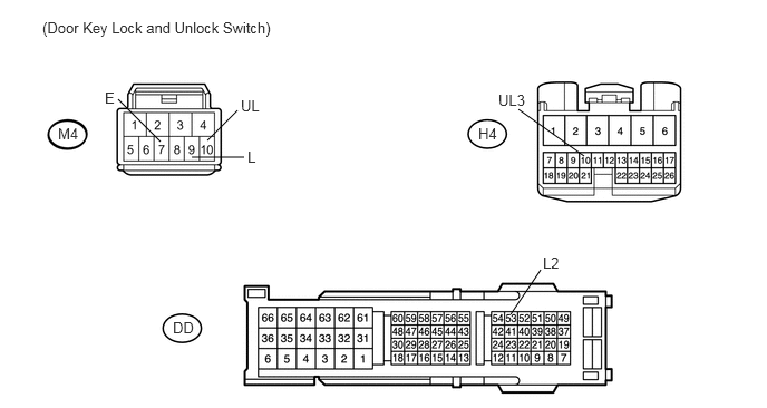

U153675E02
1.5,1.323 1.104,0.927 false 1.938,1.313 2.219,1.031 false 1.792,1.469 2.281,1.469 false 5.458,1.458 4.844,1.021 false 4.771,2.938 5.052,2.521 false 0.979,0.833 1.135,1.01 0.156,0.177 10 false E 2.25,0.906 2.448,1.083 0.198,0.177 10 false UL 2.313,1.385 2.469,1.563 0.156,0.177 10 false L 4.656,0.854 4.927,1.031 0.271,0.177 10 false UL3 5.073,2.375 5.24,2.552 0.167,0.177 10 false L2 0.542,1.167 0.844,1.344 0.302,0.177 10 false M4 1.615,2.979 1.917,3.156 0.302,0.177 10 false DD 4.469,1.167 4.698,1.333 0.229,0.167 10 false H4 0.396,0.177 2.719,0.396 2.323,0.219 10 false (Door Key Lock and Unlock Switch)

c.

Measure the resistance according to the value(s) in the table below.

Standard Resistance:
Tester Connection Condition Specified Condition
M4-9 (L) - DD-53 (L2) Always Below 1 Ω
M4-10 (UL) - H4-10 (UL3) Always Below 1 Ω
M4-7 (E) - Body ground Always Below 1 Ω
M4-10 (UL) - Body ground Always 10 kΩ or higher
M4-9 (L) - Body ground Always 10 kΩ or higher


d.

Reconnect the ECU and door lock connector.


OK

14.INSPECT FRONT DOOR LOCK LH (DOOR KEY LOCK AND UNLOCK SWITCH)

NG

REPAIR OR REPLACE HARNESS OR CONNECTOR

14.INSPECT FRONT DOOR LOCK LH (DOOR KEY LOCK AND UNLOCK SWITCH)
a.

Remove the door key lock and unlock switch (See page Vehicle Interior>DOOR LOCK>FRONT DOOR LOCK>REMOVAL).
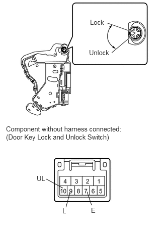

E344851E02
0.958,3.688 1.302,3.875 false 1.365,4.271 1.448,3.969 false 1.896,4.229 1.802,3.948 false 1.865,0.375 2.271,0.563 0.406,0.188 10 false Lock 1.844,1 2.333,1.208 0.49,0.208 10 false Unlock 0.76,3.594 0.979,3.781 0.219,0.188 10 false UL 1.292,4.26 1.448,4.448 0.156,0.188 10 false L 1.885,4.25 2.052,4.417 0.167,0.167 10 false E 0.125,2.573 2.583,2.938 2.458,0.365 10 false Component without harness connected: (Door Key Lock and Unlock Switch)

b.

Measure the resistance according to the value(s) in the table below.

Standard Resistance:
Tester Connection Switch Condition Specified Condition
7 (E) - 9 (L) ON (Door lock set to LOCK) Below 1 Ω
7 (E) - 9 (L)
7 (E) - 10 (UL)
OFF (Free) 10 kΩ or higher
7 (E) - 10 (UL) ON (Door lock set to UNLOCK) Below 1 Ω


c.

Reinstall the front door lock LH.


OK

REPLACE MAIN BODY ECU

NG

REPLACE FRONT DOOR LOCK LH (DOOR KEY LOCK AND UNLOCK SWITCH)