METER / GAUGE / DISPLAY METER / GAUGE SYSTEM Meter Illumination does not Dim at Night
DESCRIPTION
If the dimmer switch is turned to TAIL, HEAD or AUTO, the main body ECU sends a TAIL relay signal, panel light illumination signal, panel relay signal, and TAIL cancel OFF signal*1 to the combination meter via CAN communication. Then the meter and accessory meter become dim.
*1: w/ TAIL Cancel Switch
- HINT:
-
TAIL cancel switch: When the headlights are illuminated and the TAIL cancel switch is turned on, the meter and accessory meter do not dim.
WIRING DIAGRAM
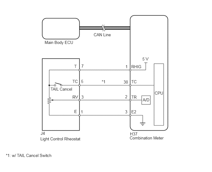
PROCEDURE
Use the Techstream to check if the CAN communication system is functioning normally (See page Vehicle Interior>METER / GAUGE / DISPLAY>METER / GAUGE SYSTEM>DTC CHECK / CLEAR).
| Result | Proceed to |
|---|---|
| CAN communication system DTC is not output | A |
| CAN communication system DTC is output | B |
A
B
Connect the Techstream to the DLC3.
Turn the ignition switch to ON.
Turn the Techstream ON.
Enter the following menus: Body Electrical / Combination Meter / Data List.
According to the display on the Techstream, read the Data List.
| Tester Display | Measurement Item/Range | Normal Condition | Diagnostic Note |
|---|---|---|---|
| TAIL Cancel SW*1 | TAIL cancel switch condition/ON or OFF | ON: TAIL cancel switch ON
OFF: TAIL cancel switch OFF |
- |
| Rheostat value | Light control rheostat switch input/Min.: 0, Max.: 100 | Light control rheostat switch is Dark (0) → Bright (100) | Unit: % |
*1: w/ TAIL Cancel Switch
- OK:
Light brightness can be changed within specified range by manual operation.
OK
NG
Remove the light control rheostat (See page Vehicle Interior>METER / GAUGE / DISPLAY>LIGHT CONTROL RHEOSTAT>REMOVAL).
Measure the resistance according to the value(s) in the table below.
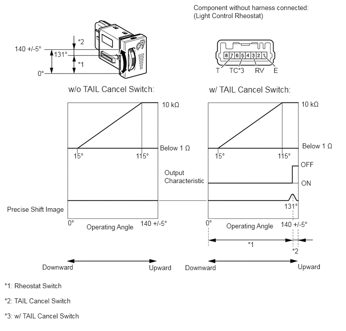
- Standard Resistance:
w/o TAIL Cancel Switch Tester Connection Condition Specified Condition 3 (RV) - 1 (E) Downward → Upward See illustration 7 (T) - 1 (E) Always 8 to 12 kΩ
w/ TAIL Cancel Switch Tester Connection Condition Specified Condition 3 (RV) - 1 (E) Downward → Upward See illustration 5 (TC) - 7 (T) Downward → Upward 10 kΩ or higher → Below 1 Ω 7 (T) - 1 (E) Always 8 to 12 kΩ
OK
NG
Disconnect the H37 meter connector.
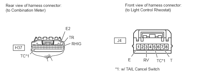
Disconnect the J4 rheostat connector.
Measure the resistance according to the value(s) in the table below.
- Standard Resistance:
w/o TAIL Cancel Switch Tester Connection Condition Specified Condition H37-1 (RHIG) - J4-7 (T) Always Below 1 Ω H37-2 (TR) - J4-3 (RV) Always Below 1 Ω H37-3 (E2) - J4-1 (E) Always Below 1 Ω
w/ TAIL Cancel Switch Tester Connection Condition Specified Condition H37-1 (RHIG) - J4-7 (T) Always Below 1 Ω H37-2 (TR) - J4-3 (RV) Always Below 1 Ω H37-3 (E2) - J4-1 (E) Always Below 1 Ω H37-38 (TC) - J4-5 (TC) Always Below 1 Ω
OK
NG