Home › Vehicle Interior › SEAT › CLIMATE CONTROL SEAT SYSTEM
RM27L0U _58 Vehicle Interior _049342 SEAT _0235878 CLIMATE CONTROL SEAT SYSTEM J

SEAT  CLIMATE CONTROL SEAT SYSTEM  Climate Control Seat System does not Operate  


DESCRIPTION

The air conditioning amplifier assembly receives seat heater switch position signals when the ignition switch ON, and then transmits airflow amount signals to each seat climate blower.

WIRING DIAGRAM
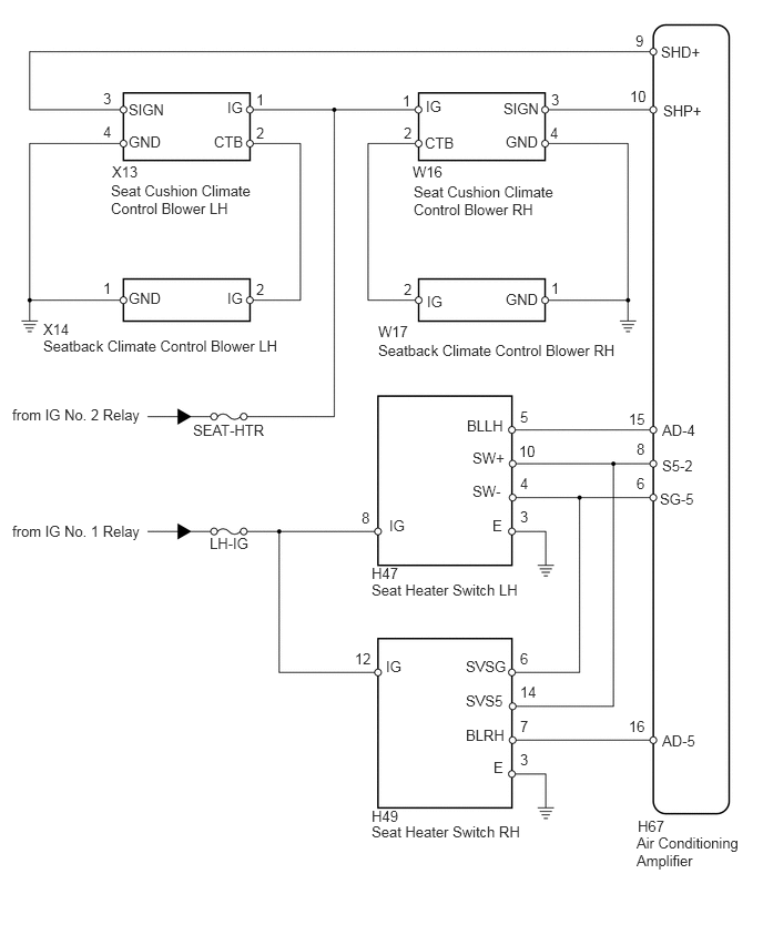
B188621E03
0.115,4.906 1.375,5.083 1.26,0.177 10 false from IG No. 1 Relay 5.906,6.74 6.146,6.906 0.24,0.167 10 false 16 3.552,3.208 5.802,3.396 2.25,0.188 10 false Seatback Climate Control Blower RH 2.135,2.719 2.333,2.927 0.198,0.208 10 false IG 1.208,2.719 1.573,2.938 0.365,0.219 10 false GND 0.406,3.01 0.646,3.198 0.24,0.188 10 false X14 3.875,1.531 4.229,1.719 0.354,0.188 10 false W16 1.052,1.531 1.302,1.708 0.25,0.177 10 false X13 4,0.917 4.198,1.125 0.198,0.208 10 false IG 4.729,0.938 5.104,1.146 0.375,0.208 10 false SIGN 3.99,1.26 4.323,1.479 0.333,0.219 10 false CTB 4.75,1.25 5.115,1.469 0.365,0.219 10 false GND 4.01,2.75 4.208,2.958 0.198,0.208 10 false IG 2.135,0.927 2.333,1.135 0.198,0.208 10 false IG 1.208,0.948 1.708,1.156 0.5,0.208 10 false SIGN 4.75,2.729 5.115,2.948 0.365,0.219 10 false GND 1.208,1.25 1.573,1.469 0.365,0.219 10 false GND 2.01,1.25 2.333,1.469 0.323,0.219 10 false CTB 6.219,6.875 6.583,7.052 0.365,0.177 10 false AD-5 6.208,0.406 6.708,0.615 0.5,0.208 10 false SHD+ 6.229,0.958 6.677,1.177 0.448,0.219 10 false SHP+ 3.49,7.583 3.813,7.771 0.323,0.188 10 false H49 3.49,5.302 3.76,5.5 0.271,0.198 10 false H47 3.656,4.854 4.052,5.073 0.396,0.219 10 false IG 3.333,6.104 3.573,6.271 0.24,0.167 10 false 12 4.885,7.052 5.125,7.219 0.24,0.167 10 false 3 4.885,6.74 5.125,6.906 0.24,0.167 10 false 7 4.885,6.417 5.125,6.583 0.24,0.167 10 false 14 4.885,4.771 5.125,4.938 0.24,0.167 10 false 3 4.625,4.854 5.021,5.073 0.396,0.219 10 false E 6.198,4.604 6.594,4.823 0.396,0.219 10 false SG-5 6.219,4.292 6.615,4.51 0.396,0.219 10 false S5-2 6.219,3.958 6.615,4.177 0.396,0.219 10 false AD-4 4.438,4.531 4.833,4.75 0.396,0.219 10 false SW- 4.438,4.219 4.833,4.438 0.396,0.219 10 false SW+ 4.385,3.917 4.781,4.135 0.396,0.219 10 false BLLH 3.625,6.177 4.021,6.396 0.396,0.219 10 false IG 4.635,7.125 5.031,7.344 0.396,0.219 10 false E 4.375,6.177 4.781,6.396 0.406,0.219 10 false SVSG 4.375,6.5 4.771,6.719 0.396,0.219 10 false SVS5 4.375,6.823 4.771,7.042 0.396,0.219 10 false BLRH 5.99,7.677 6.281,7.865 0.292,0.188 10 false H67 0.115,3.813 1.385,4.01 1.271,0.198 10 false from IG No. 2 Relay 5.906,3.854 6.104,4.021 0.198,0.167 10 false 15 5.979,4.458 6.219,4.625 0.24,0.167 10 false 6 5.979,4.135 6.219,4.302 0.24,0.167 10 false 8 5.917,0.823 6.156,0.99 0.24,0.167 10 false 10 5.969,0.302 6.208,0.469 0.24,0.167 10 false 9 1.813,3.958 2.563,4.198 0.75,0.24 10 false SEAT-HTR 1.969,5.021 2.719,5.26 0.75,0.24 10 false LH-IG 2.406,2.635 2.646,2.802 0.24,0.167 10 false 2 2.406,1.167 2.646,1.333 0.24,0.167 10 false 2 2.406,0.854 2.646,1.021 0.24,0.167 10 false 1 3.792,2.635 4.031,2.802 0.24,0.167 10 false 2 0.969,2.625 1.208,2.792 0.24,0.167 10 false 1 0.969,1.156 1.208,1.323 0.24,0.167 10 false 4 0.969,0.844 1.208,1.01 0.24,0.167 10 false 3 5.177,2.625 5.417,2.792 0.24,0.167 10 false 1 3.792,1.167 4.031,1.333 0.24,0.167 10 false 2 3.781,0.865 4.021,1.031 0.24,0.167 10 false 1 5.167,1.167 5.406,1.333 0.24,0.167 10 false 4 5.177,0.854 5.417,1.021 0.24,0.167 10 false 3 3.396,4.781 3.542,4.948 0.146,0.167 10 false 8 4.885,6.104 5.125,6.271 0.24,0.167 10 false 6 4.885,4.458 5.125,4.625 0.24,0.167 10 false 4 4.875,4.156 5.115,4.323 0.24,0.167 10 false 10 4.885,3.833 5.125,4 0.24,0.167 10 false 5 1.042,1.708 2.438,2.073 1.396,0.365 10 false Seat Cushion Climate Control Blower LH 3.885,1.719 5.24,2.063 1.354,0.344 10 false Seat Cushion Climate Control Blower RH 0.406,3.167 2.656,3.375 2.25,0.208 10 false Seatback Climate Control Blower LH 3.552,3.031 3.854,3.188 0.302,0.156 10 false W17 3.49,5.458 4.885,5.625 1.396,0.167 10 false Seat Heater Switch LH 3.49,7.729 4.917,7.927 1.427,0.198 10 false Seat Heater Switch RH 5.979,7.833 6.99,8.198 1.01,0.365 10 false Air Conditioning Amplifier

PROCEDURE

1.CHECK CLIMATE CONTROL SEAT SYSTEM OPERATION
a.

Check if the climate control seat system operates normally.

Result
Result Proceed to
Climate control does not operate on both driver and passenger sides A
Climate control does not operate on driver side B
Climate control does not operate on front passenger side C


A

2.INSPECT FUSE (LH-IG, SEAT-HTR)

B

5.CHECK HARNESS AND CONNECTOR (SEAT CLIMATE CONTROL BLOWER LH - BATTERY AND BODY GROUND)

C

11.CHECK HARNESS AND CONNECTOR (SEAT CLIMATE CONTROL BLOWER RH - BATTERY AND BODY GROUND)
2.INSPECT FUSE (LH-IG, SEAT-HTR)
a.
B443275E01
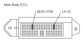
1.344,1.063 1.479,0.49 false 2.229,1.063 2.521,0.531 false 0.167,0.115 1.24,0.302 1.073,0.188 10 false Main Body ECU: 1.521,0.406 2.26,0.594 0.74,0.188 10 false SEAT-HTR 2.573,0.406 2.958,0.583 0.385,0.177 10 false LH-IG

Remove the LH-IG and SEAT-HTR fuses from the main body ECU.


b.

Measure the resistance according to the value(s) in the table below.

Standard Resistance:
Tester Connection Condition Specified Condition
LH-IG fuse Always Below 1 Ω
SEAT-HTR fuse Always Below 1 Ω


OK

3.CHECK HARNESS AND CONNECTOR (SEAT HEATER SWITCH)

NG

CHECK FOR SHORTS IN ALL HARNESSES AND CONNECTORS CONNECTED TO FUSE AND REPLACE FUSE

3.CHECK HARNESS AND CONNECTOR (SEAT HEATER SWITCH)
a.

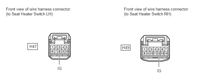
Disconnect the H47 and H49 switch connectors.
B443278E01
4.188,1.552 4.51,1.74 0.323,0.188 0.958,1.5 1.302,1.719 0.344,0.219 2.052,2.24 2.052,1.813 true 5.5,2.313 5.5,1.885 true 0.208,0.229 2.469,0.604 2.26,0.375 10 false Front view of wire harness connector: (to Seat Heater Switch LH) 4.292,0.229 6.552,0.604 2.26,0.375 10 false Front view of wire harness connector: (to Seat Heater Switch RH) 1.021,1.521 1.313,1.698 0.292,0.177 10 false H47 4.229,1.563 4.521,1.74 0.292,0.177 10 false H49 1.99,2.281 2.177,2.469 0.188,0.188 10 false IG 5.438,2.365 5.625,2.552 0.188,0.188 10 false IG


b.

Measure the voltage according to the value(s) in the table below.

Standard Voltage:
Tester Connection Switch Condition Specified Condition
H47-8 (IG) - Body ground Ignition switch ON 11 to 14 V
H49-12 (IG) - Body ground Ignition switch ON 11 to 14 V


OK

4.CHECK HARNESS AND CONNECTOR (SEAT CLIMATE CONTROL BLOWER - BATTERY AND BODY GROUND)

NG

REPAIR OR REPLACE HARNESS OR CONNECTOR

4.CHECK HARNESS AND CONNECTOR (SEAT CLIMATE CONTROL BLOWER - BATTERY AND BODY GROUND)
a.
U153262E02
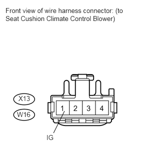
1.344,2.313 1.115,2.771 false 0.115,0.135 2.573,0.5 2.458,0.365 10 false Front view of wire harness connector: (to Seat Cushion Climate Control Blower) 0.354,2.302 0.677,2.479 0.323,0.177 10 false W16 0.385,1.969 0.656,2.146 0.271,0.177 10 false X13 0.969,2.781 1.198,3 0.229,0.219 10 false IG

Disconnect the X13 and W16 blower connectors.


b.

Measure the voltage according to the value(s) in the table below.

Standard Voltage:
Tester Connection Switch Condition Specified Condition
X13-1 (IG) - Body ground Ignition switch ON 11 to 14 V
W16-1 (IG) - Body ground Ignition switch ON 11 to 14 V


OK

REPLACE AIR CONDITIONING AMPLIFIER ASSEMBLY

NG

REPAIR OR REPLACE HARNESS OR CONNECTOR

5.CHECK HARNESS AND CONNECTOR (SEAT CLIMATE CONTROL BLOWER LH - BATTERY AND BODY GROUND)
a.
U153263E02
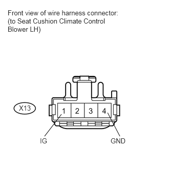
2.188,2.292 2.438,2.771 false 1.25,2.323 0.906,2.771 false 0.156,0.177 2.49,0.688 2.333,0.51 10 false Front view of wire harness connector: (to Seat Cushion Climate Control Blower LH) 0.385,2.115 0.646,2.281 0.26,0.167 10 false X13 0.813,2.781 1.042,3 0.229,0.219 10 false IG 2.25,2.781 2.604,3 0.354,0.219 10 false GND

Disconnect the X13 blower connector.


b.

Measure the voltage and resistance according to the value(s) in the table below.

Standard Voltage:
Tester Connection Switch Condition Specified Condition
X13-1 (IG) - Body ground Ignition switch ON 11 to 14 V


Standard Resistance:
Tester Connection Condition Specified Condition
X13-4 (GND) - Body ground Always Below 1 Ω


c.

Reconnect the X13 blower connector.


d.
U153264E02
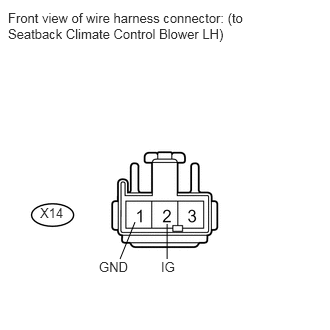
1.74,2.333 1.74,2.698 false 1.406,2.313 1.25,2.698 false 0.083,0.104 2.573,0.469 2.49,0.365 10 false Front view of wire harness connector: (to Seatback Climate Control Blower LH) 0.417,2.135 0.688,2.313 0.271,0.177 10 false X14 1.031,2.698 1.396,2.875 0.365,0.177 10 false GND 1.677,2.698 2.042,2.875 0.365,0.177 10 false IG

Disconnect the X14 blower connector.


e.

Measure the voltage and resistance according to the value(s) in the table below.

Standard Resistance:
Tester Connection Condition Specified Condition
X14-1 (GND) - Body ground Always Below 1 Ω


Standard Voltage:
Tester Connection Condition Specified Condition
X14-2 (IG) - Body ground Ignition switch ON 11 to 14 V


OK

6.INSPECT SEAT CLIMATE CONTROL BLOWER LH

NG

REPAIR OR REPLACE HARNESS OR CONNECTOR

6.INSPECT SEAT CLIMATE CONTROL BLOWER LH
a.
B443279E01
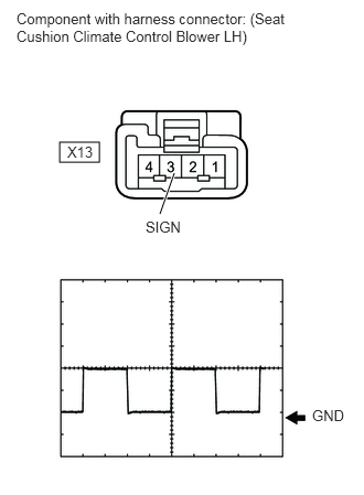
0.563,1.344 0.938,1.531 0.375,0.188 1.51,2.021 1.646,1.635 true 0.156,0.094 2.74,0.448 2.583,0.354 10 false Component with harness connector: (Seat Cushion Climate Control Blower LH) 0.635,1.354 0.917,1.531 0.281,0.177 10 false X13 1.375,2.063 1.729,2.25 0.354,0.188 10 false SIGN 2.948,3.844 3.302,4.031 0.354,0.188 10 false GND

Check the input signal waveform.

i.

Connect an oscilloscope to terminal X13-3 (SIGN) and body ground with the climate control blower connector still connected.


ii.

Check the signal waveform according to the condition(s) in the table below.

Terminal No. (Symbol) Tool setting Condition
X13-3 (SIGN) - Body ground 2 V/DIV., 500 μsec/DIV. Ignition switch ON
Seat heater switch blower side volume 3

OK:

The waveform is displayed as shown in the illustration.


Result
Result Proceed to
NG A
OK (Seat cushion blower side) B
OK (Seatback blower side) C


A

7.CHECK HARNESS AND CONNECTOR (AIR CONDITIONING AMPLIFIER - SEAT CLIMATE CONTROL BLOWER LH)

B

REPLACE SEAT CUSHION CLIMATE CONTROL BLOWER LH

C

REPLACE SEATBACK CLIMATE CONTROL BLOWER LH

7.CHECK HARNESS AND CONNECTOR (AIR CONDITIONING AMPLIFIER - SEAT CLIMATE CONTROL BLOWER LH)
a.

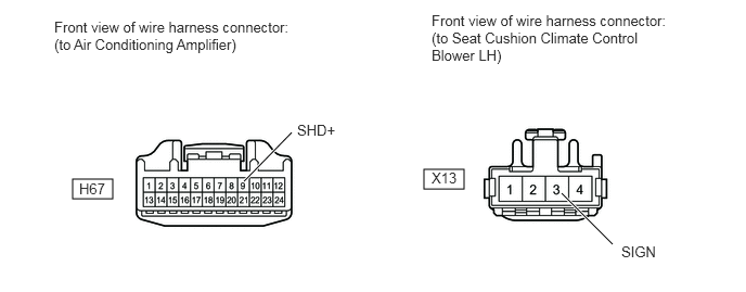
Disconnect the H67 amplifier connector.
B443280E01
0.698,1.719 1.083,1.906 0.385,0.188 4.073,1.625 4.458,1.813 0.385,0.188 2.344,1.74 2.802,1.271 true 5.396,1.854 5.885,2.344 true 4.146,0.115 6.427,0.646 2.281,0.531 10 false Front view of wire harness connector: (to Seat Cushion Climate Control Blower LH) 0.521,0.177 2.813,0.521 2.292,0.344 10 false Front view of wire harness connector: (to Air Conditioning Amplifier) 0.76,1.729 1.052,1.906 0.292,0.177 10 false H67 4.146,1.625 4.438,1.802 0.292,0.177 10 false X13 2.854,1.167 3.24,1.333 0.385,0.167 10 false SHD+ 5.969,2.333 6.354,2.5 0.385,0.167 10 false SIGN


b.

Disconnect the X13 blower connector.


c.

Measure the resistance according to the value(s) in the table below.

Standard Resistance:
Tester Connection Condition Specified Condition
H67-9 (SHD+) - X13-3 (SIGN) Always Below 1 Ω
H67-9 (SHD+) - Body ground Always 10 kΩ or higher


OK

8.CHECK HARNESS AND CONNECTOR (SEAT HEATER SWITCH LH)

NG

REPAIR OR REPLACE HARNESS OR CONNECTOR

8.CHECK HARNESS AND CONNECTOR (SEAT HEATER SWITCH LH)
a.
U153270E01
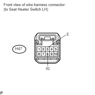
0.547,1.676 0.819,1.858 0.272,0.181 10 H47 0.129,0.085 2.538,0.409 2.410,0.324 10 Front view of wire harness connector: (to Seat Heater Switch LH) 2.409,1.157 2.552,1.311 0.143,0.153 10 E 1.655,2.398 1.882,2.551 0.227,0.154 10 IG 1.726,1.981 1.726,2.398 false 1.73,1.713 2.376,1.268 false

Disconnect the H47 switch connector.


b.

Measure the voltage and resistance according to the value(s) in the table below.

Standard Resistance:
Tester Connection Condition Specified Condition
H47-3 (E) - Body ground Always Below 1 Ω


Standard Voltage:
Tester Connection Switch Condition Specified Condition
H47-8 (IG) - Body ground Ignition switch ON 11 to 14 V


OK

9.INSPECT SEAT HEATER SWITCH LH

NG

REPAIR OR REPLACE HARNESS OR CONNECTOR

9.INSPECT SEAT HEATER SWITCH LH
a.
B191604E01
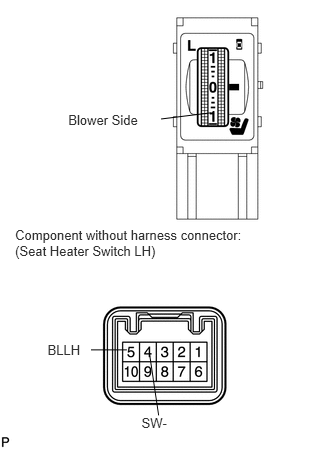
0.711,1.162 1.509,1.463 0.798,0.301 10 Blower Side 2.202,1.174 1.677,1.239 false 0.157,2.367 2.611,2.778 2.454,0.411 10 Component without harness connector: (Seat Heater Switch LH) 0.495,3.562 0.933,3.728 0.438,0.166 10 BLLH 1.474,4.326 1.912,4.492 0.438,0.166 10 SW- 1.558,3.692 1.652,4.326 false 1.321,3.644 0.947,3.644 false

Remove the seat heater switch (See page Vehicle Interior>SEAT>SEAT HEATER SWITCH(for Front Seat)>REMOVAL).


b.

Measure the resistance according to the value(s) in the table below.

Standard Resistance:
Tester Connection Condition Specified Condition
5 (BLLH) - 4 (SW-) Seat Heater switch OFF 1.54 to 2.86 kΩ
Seat heater switch blower side volume 3 Below 0.1 kΩ


OK

10.CHECK HARNESS AND CONNECTOR (SEAT HEATER SWITCH LH - AIR CONDITIONING AMPLIFIER)

NG

10.CHECK HARNESS AND CONNECTOR (SEAT HEATER SWITCH LH - AIR CONDITIONING AMPLIFIER)
a.

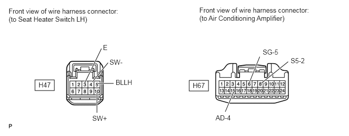
Disconnect the H67 amplifier connector.
B443290E01
0.719,1.646 1.115,1.865 0.396,0.219 3.885,1.656 4.281,1.875 0.396,0.219 1.74,1.708 2.083,1 true 1.896,1.688 2.219,1.292 true 2.01,1.719 2.333,1.719 true 1.99,1.917 1.99,2.323 true 4.792,1.906 4.625,2.302 true 5.333,1.167 5.125,1.688 true 5.917,1.271 5.375,1.708 true 0.177,0.146 2.438,0.49 2.26,0.344 10 false Front view of wire harness connector: (to Seat Heater Switch LH) 4.094,0.125 6.354,0.469 2.26,0.344 10 false Front view of wire harness connector: (to Air Conditioning Amplifier) 0.792,1.667 1.063,1.844 0.271,0.177 10 false H47 3.958,1.677 4.229,1.854 0.271,0.177 10 false H67 2.115,0.896 2.292,1.094 0.177,0.198 10 false E 2.25,1.198 2.573,1.396 0.323,0.198 10 false SW- 2.375,1.615 2.74,1.802 0.365,0.188 10 false BLLH 1.896,2.354 2.219,2.552 0.323,0.198 10 false SW+ 4.427,2.344 4.75,2.542 0.323,0.198 10 false AD-4 5.396,0.99 5.719,1.188 0.323,0.198 10 false SG-5 5.969,1.167 6.292,1.365 0.323,0.198 10 false S5-2


b.

Disconnect the H47 switch connector.


c.

Measure the resistance according to the value(s) in the table below.

Standard Resistance:
Tester Connection Condition Specified Condition
H47-3 (E) - Body ground Always Below 1 Ω
H47-4 (SW-) - H67-6 (SG-5) Always Below 1 Ω
H47-4 (SW-) - Body ground Always 10 kΩ or higher
H47-5 (BLLH) - H67-15 (AD-4) Always Below 1 Ω
H47-5 (BLLH) - Body ground Always 10 kΩ or higher
H47-10 (SW+) - H67-8 (S5-2) Always Below 1 Ω
H47-10 (SW+) - Body ground Always 10 kΩ or higher


OK

REPLACE AIR CONDITIONING AMPLIFIER ASSEMBLY

NG

REPAIR OR REPLACE HARNESS OR CONNECTOR

11.CHECK HARNESS AND CONNECTOR (SEAT CLIMATE CONTROL BLOWER RH - BATTERY AND BODY GROUND)
a.
U153261E02
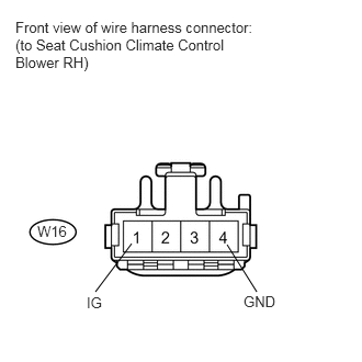
2.156,2.323 2.438,2.771 false 1.25,2.313 0.906,2.771 false 0.146,0.177 2.51,0.688 2.365,0.51 10 false Front view of wire harness connector: (to Seat Cushion Climate Control Blower RH) 0.354,2.115 0.677,2.292 0.323,0.177 10 false W16 0.823,2.792 1.052,3.01 0.229,0.219 10 false IG 2.313,2.781 2.667,3 0.354,0.219 10 false GND

Disconnect the W16 blower connector.


b.

Measure the voltage and resistance according to the value(s) in the table below.

Standard Voltage:
Tester Connection Switch Condition Specified Condition
W16-1 (IG) - Body ground Ignition switch ON 11 to 14 V


Standard Resistance:
Tester Connection Condition Specified Condition
W16-4 (GND) - Body ground Always Below 1 Ω


c.

Reconnect the W16 blower connector.


d.
U153265E02
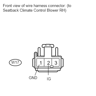
1.729,2.333 1.729,2.688 false 1.406,2.313 1.25,2.698 false 0.104,0.115 2.625,0.5 2.521,0.385 10 false Front view of wire harness connector: (to Seatback Climate Control Blower RH) 0.406,2.146 0.729,2.323 0.323,0.177 10 false W17 1.031,2.698 1.396,2.875 0.365,0.177 10 false GND 1.677,2.74 1.875,2.917 0.198,0.177 10 false IG

Disconnect the W17 blower connector.


e.

Measure the voltage and resistance according to the value(s) in the table below.

Standard Resistance:
Tester Connection Condition Specified Condition
W17-1 (GND) - Body ground Always Below 1 Ω


Standard Voltage:
Tester Connection Switch Condition Specified Condition
W17-2 (IG) - Body ground Ignition switch ON 11 to 14 V


OK

12.INSPECT SEAT CLIMATE CONTROL BLOWER RH

NG

REPAIR OR REPLACE HARNESS OR CONNECTOR

12.INSPECT SEAT CLIMATE CONTROL BLOWER RH
a.
B443279E02
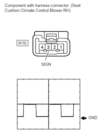
0.563,1.344 0.938,1.531 0.375,0.188 1.51,2.021 1.646,1.635 true 0.156,0.094 2.719,0.49 2.563,0.396 10 false Component with harness connector: (Seat Cushion Climate Control Blower RH) 0.604,1.354 0.906,1.531 0.302,0.177 10 false W16 1.375,2.063 1.729,2.25 0.354,0.188 10 false SIGN 2.948,3.844 3.302,4.031 0.354,0.188 10 false GND

Check the input signal waveform.

i.

Connect an oscilloscope to terminal W16-3 (SIGN) and body ground with the climate control blower connector still connected.


ii.

Check the signal waveform according to the condition(s) in the table below.

Terminal No. (Symbol) Tool setting Condition
W16-3 (SIGN) - Body ground 2 V/DIV., 500 μsec/DIV. Ignition switch ON
Seat heater switch blower side volume 3

OK:

The waveform is displayed as shown in the illustration.


Result
Result Proceed to
NG A
OK (Seat cushion blower side) B
OK (Seatback blower side) C


A

13.CHECK HARNESS AND CONNECTOR (AIR CONDITIONING AMPLIFIER - SEAT CLIMATE CONTROL BLOWER RH)

B

REPLACE SEAT CUSHION CLIMATE CONTROL BLOWER RH

C

REPLACE SEATBACK CLIMATE CONTROL BLOWER RH

13.CHECK HARNESS AND CONNECTOR (AIR CONDITIONING AMPLIFIER - SEAT CLIMATE CONTROL BLOWER RH)
a.

Disconnect the H67 amplifier connector.
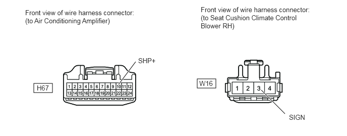
B443280E02
0.698,1.719 1.083,1.906 0.385,0.188 4.073,1.625 4.458,1.813 0.385,0.188 2.448,1.74 2.802,1.271 true 5.396,1.854 5.885,2.344 true 4.146,0.115 6.427,0.646 2.281,0.531 10 false Front view of wire harness connector: (to Seat Cushion Climate Control Blower RH) 0.521,0.177 2.813,0.521 2.292,0.344 10 false Front view of wire harness connector: (to Air Conditioning Amplifier) 0.76,1.729 1.052,1.906 0.292,0.177 10 false H67 4.115,1.635 4.406,1.813 0.292,0.177 10 false W16 2.854,1.167 3.24,1.333 0.385,0.167 10 false SHP+ 5.969,2.333 6.354,2.5 0.385,0.167 10 false SIGN


b.

Disconnect the W16 blower connector.


c.

Measure the resistance according to the value(s) in the table below.

Standard Resistance:
Tester Connection Condition Specified Condition
H67-10 (SHP+) - W16-3 (SIGN) Always Below 1 Ω
H67-10 (SHP+) - Body ground Always 10 kΩ or higher


OK

14.CHECK HARNESS AND CONNECTOR (SEAT HEATER SWITCH RH)

NG

REPAIR OR REPLACE HARNESS OR CONNECTOR

14.CHECK HARNESS AND CONNECTOR (SEAT HEATER SWITCH RH)
a.
U153272E02
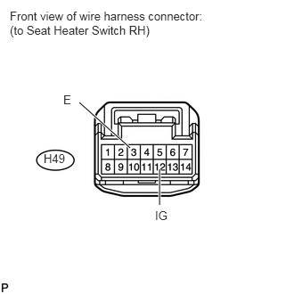
1.865,1.979 1.865,2.396 true 1.521,1.729 0.927,1.198 true 1.813,2.438 2.031,2.635 0.219,0.198 10 false IG 0.74,1.083 0.885,1.281 0.146,0.198 10 false E 0.51,1.771 0.781,1.948 0.271,0.177 10 false H49 0.115,0.104 2.396,0.49 2.281,0.385 10 false Front view of wire harness connector: (to Seat Heater Switch RH)

Disconnect the H49 switch connector.


b.

Measure the voltage and resistance according to the value(s) in the table below.

Standard Resistance:
Tester Connection Condition Specified Condition
H49-3 (E) - Body ground Always Below 1 Ω


Standard Voltage:
Tester Connection Switch Condition Specified Condition
H49-12 (IG) - Body ground Ignition switch ON 11 to 14 V


OK

15.INSPECT SEAT HEATER SWITCH RH

NG

REPAIR OR REPLACE HARNESS OR CONNECTOR

15.INSPECT SEAT HEATER SWITCH RH
a.
B191607E01
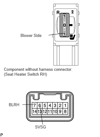
0.704,1.123 1.502,1.424 0.798,0.301 10 Blower Side 2.195,1.134 1.67,1.2 false 0.132,2.279 2.587,2.690 2.454,0.411 10 Component without harness connector: (Seat Heater Switch RH) 0.302,3.488 0.740,3.654 0.438,0.166 10 BLRH 1.203,4.252 1.640,4.418 0.438,0.166 10 SVSG 1.373,3.627 1.467,4.252 false 1.146,3.57 0.771,3.57 false

Remove the seat heater switch (See page Vehicle Interior>SEAT>SEAT HEATER SWITCH(for Front Seat)>REMOVAL).


b.

Measure the resistance according to the value(s) in the table below.

Standard Resistance:
Tester Connection Condition Specified Condition
7 (BLRH) - 6 (SVSG) Seat Heater switch OFF 1.54 to 2.86 kΩ
Seat heater switch blower side volume 3 Below 0.1 kΩ


OK

16.CHECK HARNESS AND CONNECTOR (SEAT HEATER SWITCH RH - AIR CONDITIONING AMPLIFIER)

NG

16.CHECK HARNESS AND CONNECTOR (SEAT HEATER SWITCH RH - AIR CONDITIONING AMPLIFIER)
a.

Disconnect the H67 amplifier connector.
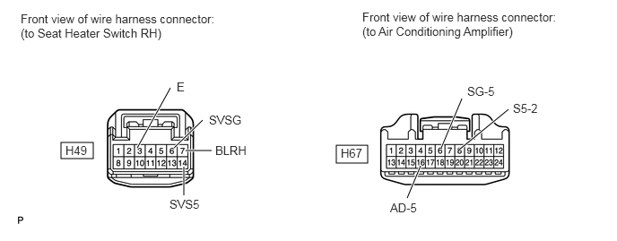
B443291E01
0.708,1.656 1.083,1.844 0.375,0.188 3.906,1.688 4.271,1.896 0.365,0.208 1.594,1.719 1.979,1.021 true 2.021,1.719 2.354,1.396 true 2.156,1.75 2.458,1.75 true 2.135,1.938 2.135,2.271 true 4.885,1.927 4.729,2.302 true 5.365,1.146 5.125,1.719 true 5.906,1.271 5.333,1.74 true 0.24,0.135 2.5,0.5 2.26,0.365 10 false Front view of wire harness connector: (to Seat Heater Switch RH) 4.208,0.115 6.469,0.479 2.26,0.365 10 false Front view of wire harness connector: (to Air Conditioning Amplifier) 0.76,1.667 1.052,1.854 0.292,0.188 10 false H49 3.958,1.698 4.25,1.885 0.292,0.188 10 false H67 2.052,0.927 2.344,1.115 0.292,0.188 10 false E 2.427,1.313 2.865,1.5 0.438,0.188 10 false SVSG 2.5,1.667 2.938,1.854 0.438,0.188 10 false BLRH 1.969,2.292 2.406,2.479 0.438,0.188 10 false SVS5 4.531,2.333 4.865,2.521 0.333,0.188 10 false AD-5 5.427,0.979 5.76,1.167 0.333,0.188 10 false SG-5 5.958,1.177 6.292,1.365 0.333,0.188 10 false S5-2


b.

Disconnect the H49 switch connector.


c.

Measure the resistance according to the value(s) in the table below.

Standard Resistance:
Tester Connection Condition Specified Condition
H49-3 (E) - Body ground Always Below 1 Ω
H49-6 (SVSG) - H67-6 (SG- 5) Always Below 1 Ω
H49-6 (SVSG) - Body ground Always 10 kΩ or higher
H49-7 (BLRH) - H67-16 (AD-5) Always Below 1 Ω
H49-7 (BLRH) - Body ground Always 10 kΩ or higher
H49-14 (SVS5) - H67-8 (S5-2) Always Below 1 Ω
H49-14 (SVS5) - Body ground Always 10 kΩ or higher


OK

REPLACE AIR CONDITIONING AMPLIFIER ASSEMBLY

NG

REPAIR OR REPLACE HARNESS OR CONNECTOR