SEAT REAR POWER SEAT CONTROL SYSTEM Indicator Circuit
DESCRIPTION
The indicator lights is built into the fold seat switch. This indicator light receives power from the fold seat control ECU. It comes on or blinks when the system detects that an object is caught or when the seat operation conditions are not met.
WIRING DIAGRAM
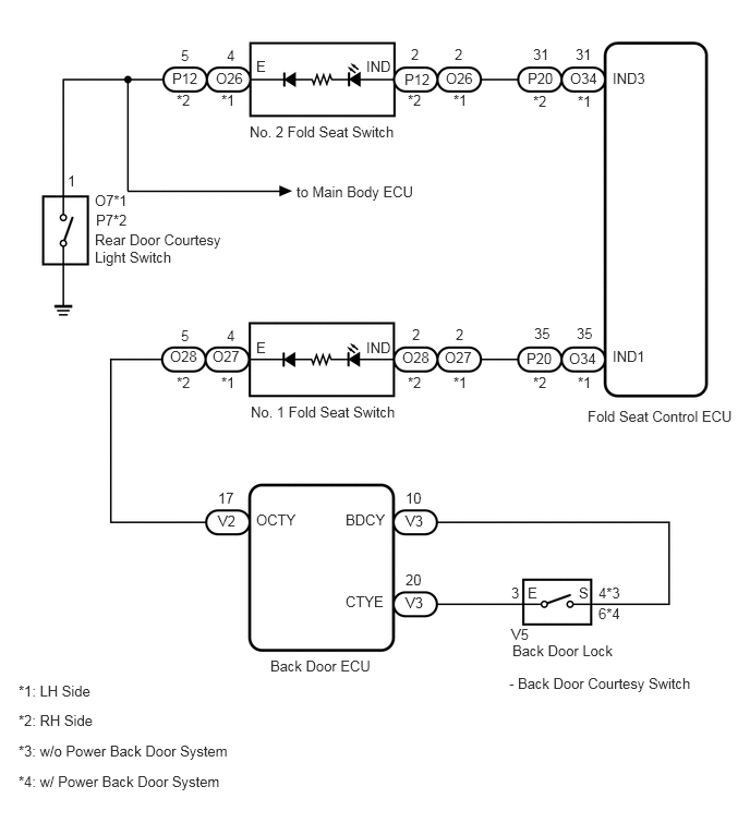
PROCEDURE
Perform troubleshooting in accordance with the chart below.
| Result | Proceed to |
|---|---|
| No. 1 fold seat switch indicator circuit | A |
| No. 2 fold seat switch indicator circuit | B |
A
B
Connect the Techstream to the DLC3.
Turn the ignition switch to ON.
Turn the Techstream ON.
Enter the following menus: Body Electrical / Back Door P/W / Data List.
According to the display on the Techstream, read the Data List.
| Tester Display | Measurement Item/Range | Normal Condition | Diagnostic Note |
|---|---|---|---|
| Back Door Courtesy Switch | Back Door Courtesy Switch / ON or OFF | ON: Back door opened
OFF: Back door closed |
- |
- OK:
When back door courtesy switch operation is performed, the results are the same as above.
OK
NG
Remove the No. 1 fold seat switch (See page Vehicle Interior>SEAT>POWER SEAT SWITCH(for Rear No. 2 Seat)>REMOVAL).
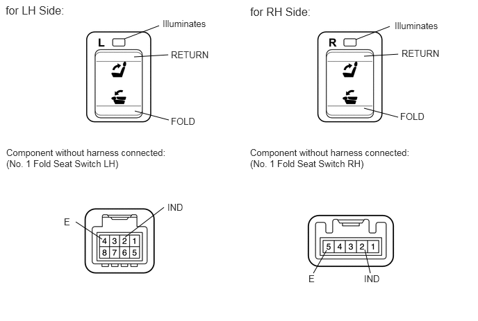
Apply battery voltage to the switch connector, and check that the fold seat switch assembly illuminates.
- OK:
LH Side Measurement Condition Switch Condition Specified Condition Battery positive (+) → 2 (IND)
Battery negative (-) → 4 (E)FOLD Illuminates RETURN Illuminates
RH Side Measurement Condition Switch Condition Specified Condition Battery positive (+) → 2 (IND)
Battery negative (-) → 5 (E)FOLD Illuminates RETURN Illuminates
OK
NG
Disconnect the V2 ECU connector.
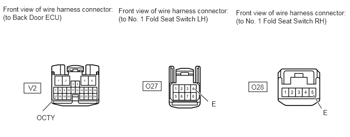
Disconnect the O27 or O28 switch connector.
Measure the resistance according to the value(s) in the table below.
- Standard Resistance:
LH Side Tester Connection Condition Specified Condition V2-17 (OCTY) - O27-4 (E) Always Below 1 Ω V2-17 (OCTY) - Body ground Always 10 kΩ or higher
RH Side Tester Connection Condition Specified Condition V2-17 (OCTY) - O28-5 (E) Always Below 1 Ω V2-17 (OCTY) - Body ground Always 10 kΩ or higher
OK
NG
Disconnect the O34 or P20 ECU connector.
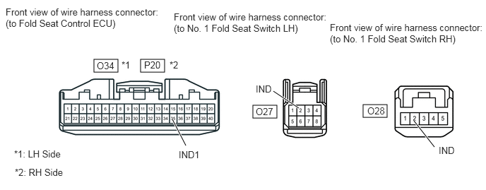
Disconnect the O27 or O28 switch connector.
Measure the resistance according to the value(s) in the table below.
- Standard Resistance:
LH Side Tester Connection Condition Specified Condition O34-35 (IND1) - O27-2 (IND) Always Below 1 Ω O34-35 (IND1) - Body ground Always 10 kΩ or higher
RH Side Tester Connection Condition Specified Condition P20-35 (IND1) - O28-2 (IND) Always Below 1 Ω P20-35 (IND1) - Body ground Always 10 kΩ or higher
OK
NG
Connect the Techstream to the DLC3.
Turn the ignition switch to ON.
Turn the Techstream ON.
Enter the following menus: Body Electrical / Main Body / Data List.
According to the display on the Techstream, read the Data List.
| Tester Display | Measurement Item/Range | Normal Condition | Diagnostic Note |
|---|---|---|---|
| RL Door Courtesy SW | Rear door courtesy light switch LH signal / ON or OFF | ON: Rear door courtesy light switch LH ON
OFF: Rear door courtesy light switch LH OFF |
- |
| RR Door Courtesy SW | Rear door courtesy light switch RH signal / ON or OFF | ON: Rear door courtesy light switch RH ON
OFF: Rear door courtesy light switch RH OFF |
- |
- OK:
When rear door courtesy light switch operation is performed, the results are the same as above.
OK
NG
Remove the No. 2 fold seat switch (See page Vehicle Interior>SEAT>POWER SEAT SWITCH(for Rear No. 2 Seat)>REMOVAL).
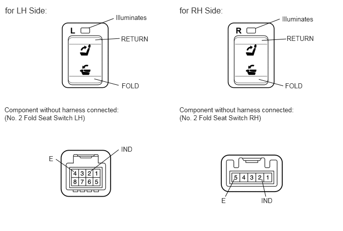
Apply battery voltage to the switch connector, and check that the fold seat switch assembly illuminates.
- OK:
LH Side Measurement Condition Switch Condition Specified Condition Battery positive (+) → 2 (IND)
Battery negative (-) → 4 (E)FOLD Illuminates RETURN Illuminates
RH Side Measurement Condition Switch Condition Specified Condition Battery positive (+) → 2 (IND)
Battery negative (-) → 5 (E)FOLD Illuminates RETURN Illuminates
OK
NG
Disconnect the O7 or P7 switch connector.
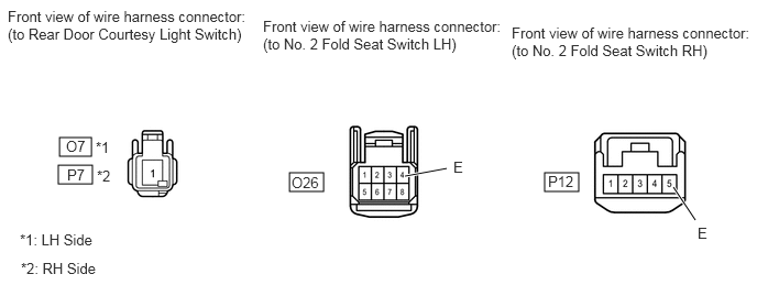
Disconnect the O26 or P12 switch connector.
Measure the resistance according to the value(s) in the table below.
- Standard Resistance:
LH Side Tester Connection Condition Specified Condition O7-1 - O26-4 (E) Always Below 1 Ω O7-1 - Body ground Always 10 kΩ or higher
RH Side Tester Connection Condition Specified Condition P7-1 - P12-5 (E) Always Below 1 Ω P7-1 - Body ground Always 10 kΩ or higher
OK
NG
Disconnect the O34 or P20 ECU connector.
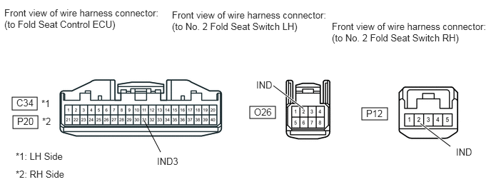
Disconnect the O26 or P12 switch connector.
Measure the resistance according to the value(s) in the table below.
- Standard Resistance:
LH Side Tester Connection Condition Specified Condition O34-31 (IND3) - O26-2 (IND) Always Below 1 Ω O34-31 (IND3) - Body ground Always 10 kΩ or higher
RH Side Tester Connection Condition Specified Condition P20-31 (IND3) - P12-2 (IND) Always Below 1 Ω P20-31 (IND3) - Body ground Always 10 kΩ or higher
OK
NG