Home › Vehicle Exterior › WINDOW / GLASS › POWER WINDOW CONTROL SYSTEM
RM27L0U _59 Vehicle Exterior _049347 WINDOW / GLASS _0235939 POWER WINDOW CONTROL SYSTEM J

WINDOW / GLASS  POWER WINDOW CONTROL SYSTEM  Manual Up / Down Function Via Back Door Lock Key Cylinder does not Operate  


DESCRIPTION

If the manual UP/DOWN function via the back door lock key cylinder does not operate, the back door lock key cylinder, the harness and connector, the back door ECU may be abnormal.

WIRING DIAGRAM
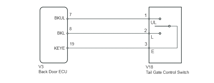
B443134E01
2.323,0.406 2.438,0.583 0.115,0.177 10 false 7 2.323,0.885 2.438,1.063 0.115,0.177 10 false 8 2.333,1.396 2.49,1.573 0.156,0.177 10 false 19 1.823,0.521 2.188,0.698 0.365,0.177 10 false BKUL 1.917,1.031 2.198,1.208 0.281,0.177 10 false BKL 1.813,1.542 2.208,1.708 0.396,0.167 10 false KEYE 4.833,0.417 4.948,0.594 0.115,0.177 11 false 1 4.833,0.927 4.948,1.104 0.115,0.177 11 false 2 4.844,1.385 4.958,1.563 0.115,0.177 11 false 3 5.042,0.656 5.25,0.833 0.208,0.177 11 false UL 5.052,1.146 5.188,1.333 0.135,0.188 11 false L 5.063,1.635 5.198,1.823 0.135,0.188 11 false E 1.292,2.167 1.479,2.344 0.188,0.177 10 false V3 1.292,2.333 2.281,2.521 0.99,0.188 10 false Back Door ECU 4.885,2.177 5.167,2.354 0.281,0.177 10 false V18 4.885,2.354 6.385,2.521 1.5,0.167 10 false Tail Gate Control Switch

PROCEDURE

1.CHECK BACK DOOR WINDOW OPERATION
a.

Check that the back door power window operates via the back door power window switch.

OK:

Manual UP/DOWN function operates normally.


OK

2.READ VALUE USING TECHSTREAM

NG

2.READ VALUE USING TECHSTREAM
a.

Connect the Techstream to the DLC3.


b.

Turn the ignition switch to ON.


c.

Turn the Techstream on.


d.

Enter the following menus: Body Electrical / Back Door P/W / Data List.


e.

According to the display on the Techstream, read the Data List.

Back Door P/W
Tester Display Measurement Item/Range Normal Condition Diagnostic Note
Key Switch Operation Locked Back door key lock and unlock switch signal / ON or OFF ON: Back door lock key cylinder is turned to unlock
OFF: Key is in back door lock key cylinder (original position)
-
Key Switch Operation Unlocked Back door key lock and unlock switch signal / ON or OFF ON: Back door lock key cylinder is turned to unlock
OFF: Key is in back door lock key cylinder (original position)
-


OK:

The Techstream display changes normally when tail gate control switch is operated.


OK

REPLACE BACK DOOR ECU

NG

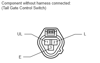
3.INSPECT TAIL GATE CONTROL SWITCH
a.
B191471E01
0.051,0.025 2.586,0.348 2.535,0.323 10 Component without harness connected: (Tail Gate Control Switch) 0.593,1.099 0.808,1.253 0.215,0.153 10 UL 0.645,1.895 0.785,2.053 0.139,0.158 10 E 2.882,1.099 3.001,1.254 0.119,0.155 10 L 0.837,1.184 1.081,1.184 1.081,1.184 1.589,1.452 false 0.797,1.976 1.04,1.976 1.04,1.976 1.712,1.686 false 2.818,1.19 2.574,1.19 2.574,1.19 1.932,1.446 false

Remove the tail gate control switch (See page Vehicle Exterior>DOOR / HATCH>BACK DOOR>DISASSEMBLY).


b.

Insert the key into the key cylinder.


c.

Measure the resistance according to the value(s) in the table below.

Standard Resistance:
Tester Connection Switch Condition Specified Condition
1 (UL) - 3 (E) Turn key to unlock position Below 1 Ω
Turn key to lock position 10 kΩ or higher
2 (L) - 3 (E) Turn key to unlock position 10 kΩ or higher
Turn key to lock position Below 1 Ω


d.

Reinstall the tail gate control switch.


OK

4.INSPECT HARNESS AND CONNECTOR (BACK DOOR ECU - TAIL GATE CONTROL SWITCH)

NG

REPLACE TAIL GATE CONTROL SWITCH

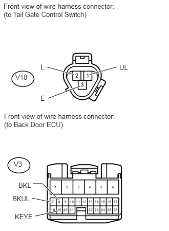
4.INSPECT HARNESS AND CONNECTOR (BACK DOOR ECU - TAIL GATE CONTROL SWITCH)
a.
U153258E02
0.948,1.354 1.51,1.51 true 0.979,1.99 1.635,1.74 true 2.375,1.354 1.823,1.51 true 0.667,3.719 0.865,3.719 0.865,3.719 1.188,4.042 true 0.656,4.01 1.052,4.094 true 0.708,4.375 1.177,4.271 true 0.073,0.042 2.458,0.417 2.385,0.375 10 false Front view of wire harness connector: (to Tail Gate Control Switch) 0.313,1.479 0.604,1.646 0.292,0.167 10 false V18 0.823,1.271 0.958,1.448 0.135,0.177 10 false L 2.427,1.281 2.688,1.448 0.26,0.167 10 false UL 0.823,1.906 0.958,2.063 0.135,0.156 10 false E 0.083,2.271 2.469,2.646 2.385,0.375 10 false Front view of wire harness connector: (to Back Door ECU) 0.281,3.24 0.573,3.406 0.292,0.167 10 false V3 0.25,3.938 0.625,4.094 0.375,0.156 10 false BKUL 0.375,3.667 0.656,3.833 0.281,0.167 10 false BKL 0.302,4.302 0.729,4.469 0.427,0.167 10 false KEYE

Disconnect the V3 back door ECU connector.


b.

Disconnect the V18 tail gate control switch connector.


c.

Measure the resistance according to the value(s) in the table below.

Standard Resistance:
Tester Connection Condition Specified Condition
V3-7 (BKUL) - V18-1 (UL) Always Below 1 Ω
V3-8 (BKL) - V18-2 (L) Always Below 1 Ω
V3-19 (KEYE) - V18-3 (E) Always Below 1 Ω
V18-1 (UL) - Body ground Always 10 kΩ or higher
V18-2 (L) - Body ground Always 10 kΩ or higher
V18-3 (E) - Body ground Always 10 kΩ or higher


d.

Reconnect the tail gate control switch connector.


e.

Reconnect the back door ECU connector.


OK

REPLACE BACK DOOR ECU

NG

REPAIR OR REPLACE HARNESS OR CONNECTOR