SLIDING ROOF / CONVERTIBLE SLIDING ROOF SYSTEM Sliding Roof Control Switch Circuit
DESCRIPTION
If either the sliding function or tilt function does not operate, there may be a malfunction in the sliding roof switch circuit.
WIRING DIAGRAM
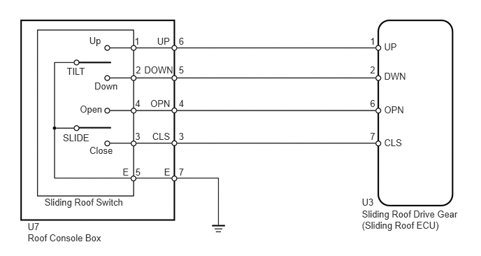
PROCEDURE
Connect the Techstream to the DLC3.
Turn the ignition switch to ON.
Turn the Techstream ON.
Enter the following menus: Body Electrical / Sliding Roof / Active Test.
According to the display on the Techstream, perform the Active Test.
| Tester Display | Test Part | Control Range | Diagnostic Note |
|---|---|---|---|
| Slide Roof | Operate sliding roof SLIDE CLOSE/TILT UP or SLIDE OPEN/TILT DOWN | CLOS/UP: Sliding roof SLIDE CLOSE or TILT UP operation occurs
OPN/DWN: Sliding roof SLIDE OPEN or TILT DOWN operation occurs OFF: Sliding roof is not operating |
- |
- OK:
Sliding roof operates normally.
OK
NG
Connect the Techstream to the DLC3.
Turn the ignition switch to ON.
Turn the Techstream ON.
Enter the following menus: Body Electrical / Sliding Roof / Data List.
According to the display on the Techstream, read the Data List.
| Tester Display | Test Part | Control Range | Diagnostic Note |
|---|---|---|---|
| Open Switch | Sliding roof open switch signal/ON or OFF | ON: SLIDE switch is pressed to open
OFF: SLIDE switch is not pressed to open |
- |
| Close Switch | Sliding roof close switch signal/ON or OFF | ON: SLIDE switch is pressed to close
OFF: SLIDE switch is not pressed to close |
- |
| Up Switch | Sliding roof up switch signal/ON or OFF | ON: TILT switch is pressed to up
OFF: TILT switch is not pressed to up |
- |
| Down Switch | Sliding roof down switch signal/ON or OFF | ON: TILT switch is pressed to down
OFF: TILT switch is not pressed to down |
- |
- OK:
The Techstream displays as shown in the table according to the operation of each switch.
OK
NG
Remove the sliding roof switch (See page Vehicle Exterior>SLIDING ROOF / CONVERTIBLE>SLIDING ROOF SWITCH ASSEMBLY>REMOVAL).
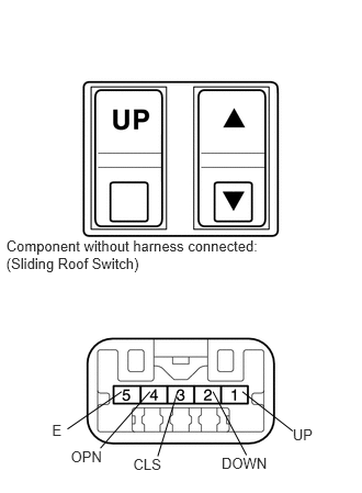
Measure the resistance according to the value(s) in the table below.
- Standard Resistance:
Tester Connection Switch Condition Specified Condition 1 (UP) - 5 (E) TILT switch is pressed to up Below 1 Ω TILT switch is not pressed to up 10 kΩ or higher 2 (DOWN) - 5 (E) TILT switch is pressed to down Below 1 Ω TILT switch is not pressed to down 10 kΩ or higher 3 (CLS) - 5 (E) SLIDE switch is pressed to close Below 1 Ω SLIDE switch is not pressed to close 10 kΩ or higher 4 (OPN) - 5 (E) SLIDE switch is pressed to open Below 1 Ω SLIDE switch is not pressed to open 10 kΩ or higher
OK
NG
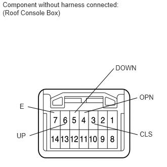
Remove the roof console box with sliding roof switch (See page Vehicle Interior>INTERIOR PANELS / TRIM>OVERHEAD CONSOLE BOX>REMOVAL).
Measure the resistance according to the value(s) in the table below.
- Standard Resistance:
Tester Connection Switch Condition Specified Condition 3 (CLS) - 7 (E) SLIDE switch is pressed to close Below 1 Ω SLIDE switch is not pressed to close 10 kΩ or higher 4 (OPN) - 7 (E) SLIDE switch is pressed to open Below 1 Ω SLIDE switch is not pressed to open 10 kΩ or higher 5 (DOWN) - 7 (E) TILT switch is pressed to down Below 1 Ω TILT switch is not pressed to down 10 kΩ or higher 6 (UP) - 7 (E) TILT switch is pressed to up Below 1 Ω TILT switch is not pressed to up 10 kΩ or higher
OK
NG
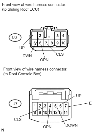
Disconnect the U3 ECU connector.
Disconnect the U7 switch connector.
Measure the resistance according to the value(s) in the table below.
- Standard Resistance:
Tester Connection Condition Specified Condition U7-3 (CLS) - U3-7 (CLS) Always Below 1 Ω U7-3 (CLS) - Body ground Always 10 kΩ or higher U7-4 (OPN) - U3-6 (OPN) Always Below 1 Ω U7-4 (OPN) - Body ground Always 10 kΩ or higher U7-5 (DOWN) - U3-2 (DWN) Always Below 1 Ω U7-5 (DOWN) - Body ground Always 10 kΩ or higher U7-6 (UP) - U3-1 (UP) Always Below 1 Ω U7-6 (UP) - Body ground Always 10 kΩ or higher U7-7 (E) - Body ground Always Below 1 Ω
OK
NG