SLIDING ROOF / CONVERTIBLE SLIDING ROOF HOUSING INSTALLATION
PROCEDURE

 63203F
1.INSTALL SLIDING ROOF HOUSING SUB-ASSEMBLY
for Type A:
Temporarily install the housing with the 10 bolts (vehicle body side) and 6 nuts.
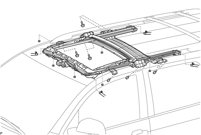
Tighten the 6 nuts.
- Torque:
- 5.5 N*m (56 kgf*cm, 49 in.*lbf)
Tighten the 10 bolts.
- Torque:
- 5.5 N*m (56 kgf*cm, 49 in.*lbf)
for Type B:
Temporarily install the housing with the 10 bolts (vehicle body side) and 6 nuts.
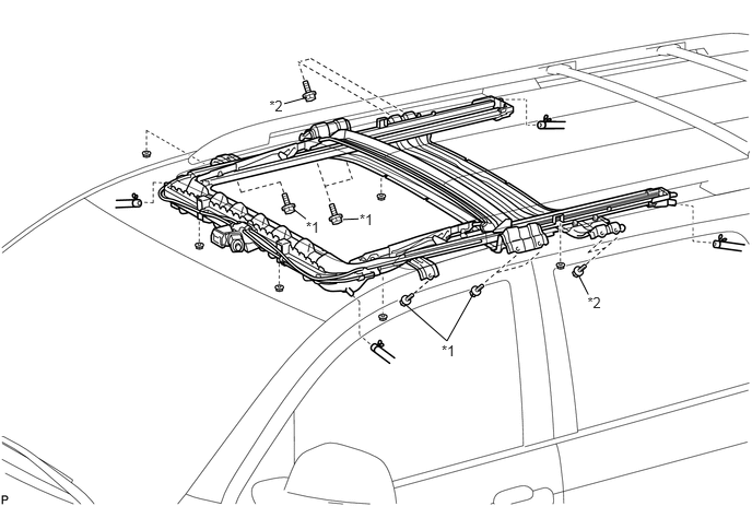
| *1 | Bolt A | *2 | Bolt B |
Tighten the 6 nuts.
- Torque:
- 5.5 N*m (56 kgf*cm, 49 in.*lbf)
Tighten the 10 bolts.
- Torque:
- Bolt A : 8.0 N*m (82 kgf*cm, 71 in.*lbf)
- Torque:
- Bolt B : 5.5 N*m (56 kgf*cm, 49 in.*lbf)
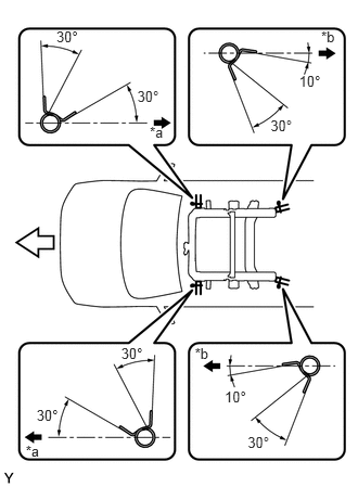
Connect the 4 sliding roof drain hoses.
| *a | Front Side |
| *b | Outer Side |

|
Front |
- HINT:
-
Install the hose so that the direction of the clip is as indicated in the illustration.
63251H
2.INSTALL SLIDING ROOF WEATHERSTRIP
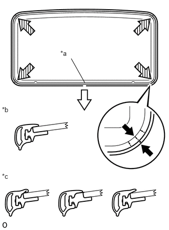
Install the sliding roof weatherstrip as described below.
| *a | Cutout |
| *b | Correct |
| *c | Incorrect |
|
|
Rear Side |
Engage each corner of the weatherstrip so that each weatherstrip mark is aligned with the sliding roof glass center mark. After attaching the entire weatherstrip, check that all weatherstrip marks are within the sliding roof glass end marks.
Make sure that the weatherstrip cutout is toward the rear side of the vehicle and centered.
Make sure that the weatherstrip is securely installed as shown in the illustration.
63201G
3.INSTALL SLIDING ROOF GLASS SUB-ASSEMBLY
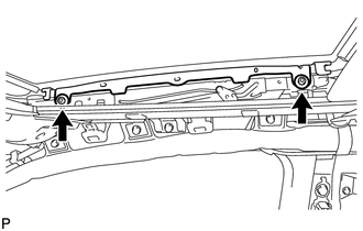
Using a T25 "TORX" socket wrench, temporarily install the glass with the 4 bolts.
Perform a level check.
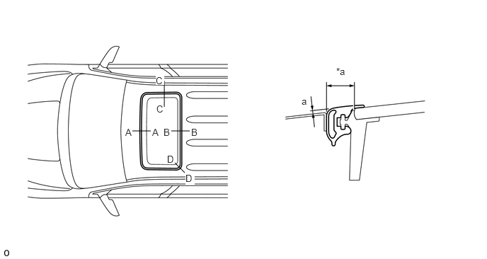
| *a | Even | - | - |
Check the difference in the level between the roof panel and the upper surface of the weatherstrip labeled "a" when the sliding roof glass is fully closed.
- Standard:
Area Measurement A - A 0 +/-1.5 mm (0 +/-0.0591 in.) B - B C - C D - D
- HINT:
-
"+" represents the condition that the glass is above the panel level. "-" represents the condition that the glass is below the panel level.
Perform a gap check.
Check the gap between the roof panel and roof glass.
- NOTICE:
-
The gap must be even all around.
Tighten the 2 bolts.
- Torque:
- 4.0 N*m (41 kgf*cm, 35 in.*lbf)
4.CHECK FOR WATER LEAK
After adjusting the sliding roof glass sub-assembly, check for water leaks.
If there are any leaks, readjust the sliding roof glass sub-assembly.
63217K
5.INSTALL SLIDING ROOF SIDE GARNISH RH
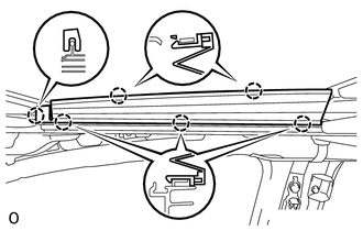
Attach the 6 claws to install the sliding roof side garnish.
63218M
6.INSTALL SLIDING ROOF SIDE GARNISH LH
- HINT:
-
Use the same procedure for the RH side and LH side.
62170A
7.INSTALL CURTAIN SHIELD AIRBAG ASSEMBLY RH
Install the curtain shield airbag (See page Vehicle Interior>SUPPLEMENTAL RESTRAINT SYSTEMS>CURTAIN SHIELD AIRBAG ASSEMBLY>INSTALLATION).
62180A
8.INSTALL CURTAIN SHIELD AIRBAG ASSEMBLY LH
- HINT:
-
Use the same procedure for the RH side and LH side.
63311C
9.INSTALL ROOF HEADLINING ASSEMBLY
Install the roof headlining (See page Vehicle Interior>INTERIOR PANELS / TRIM>ROOF HEADLINING>INSTALLATION).
10.CONNECT CABLE TO NEGATIVE BATTERY TERMINAL
- NOTICE:
-
When disconnecting the cable, some systems need to be initialized after the cable is reconnected (See page General>INTRODUCTION>REPAIR INSTRUCTION>INITIALIZATION).
- Torque:
- 5.4 N*m (55 kgf*cm, 48 in.*lbf)
11.INSPECT SRS WARNING LIGHT