Home › Vehicle Exterior › WIPER / WASHER › WIPER AND WASHER SYSTEM
RM27L0U _59 Vehicle Exterior _049351 WIPER / WASHER _0235977 WIPER AND WASHER SYSTEM J

WIPER / WASHER  WIPER AND WASHER SYSTEM  Rear Wiper Motor Circuit  


DESCRIPTION

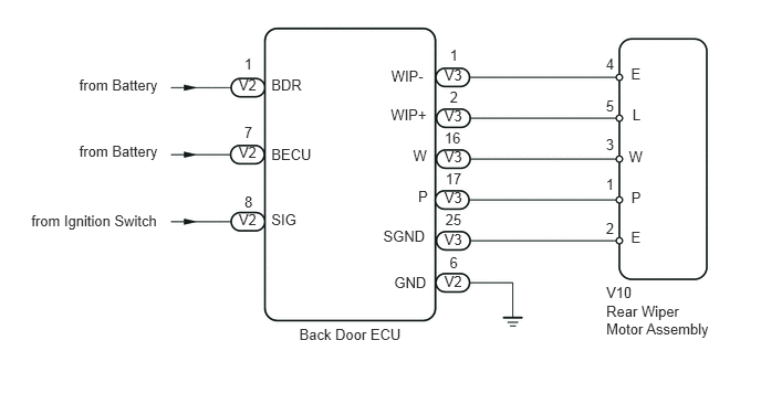
The back door ECU controls the rear wiper motor.

WIRING DIAGRAM
E152590E02
0.746,0.716 1.544,0.886 0.799,0.170 10 from Battery 0.746,1.345 1.544,1.515 0.799,0.170 10 from Battery 0.294,2.004 1.541,2.171 1.247,0.166 10 from Ignition Switch 2.248,0.72 2.450,0.878 0.202,0.158 10 V2 2.248,1.356 2.450,1.515 0.202,0.158 10 V2 2.248,1.993 2.450,2.151 0.202,0.158 10 V2 4.184,2.573 4.386,2.731 0.202,0.158 10 V2 4.184,2.174 4.386,2.332 0.202,0.158 10 V3 4.184,0.622 4.386,0.780 0.202,0.158 10 V3 4.184,1.01 4.386,1.168 0.202,0.158 10 V3 4.184,1.398 4.386,1.556 0.202,0.158 10 V3 4.184,1.786 4.386,1.944 0.202,0.158 10 V3 2.3,0.526 2.399,0.684 0.100,0.158 10 1 2.3,1.166 2.399,1.313 0.100,0.147 10 7 2.302,1.818 2.397,1.961 0.096,0.143 10 8 4.236,0.439 4.335,0.597 0.099,0.158 10 1 4.236,0.836 4.335,0.977 0.099,0.141 10 2 4.186,1.224 4.383,1.382 0.197,0.158 10 16 4.195,1.606 4.374,1.753 0.179,0.148 10 17 4.194,1.992 4.376,2.143 0.182,0.151 10 25 4.234,2.401 4.337,2.559 0.103,0.158 10 6 2.818,3.075 3.833,3.241 1.015,0.166 10 Back Door ECU 2.555,0.718 2.898,0.884 0.343,0.166 10 BDR 2.555,1.37 2.984,1.529 0.430,0.158 10 BECU 2.555,1.994 2.827,2.149 0.272,0.155 10 SIG 3.684,0.633 4.051,0.799 0.367,0.166 10 WIP- 3.68,1.002 4.051,1.164 0.371,0.162 10 WIP+ 3.89,1.382 4.053,1.544 0.162,0.162 10 W 3.938,1.767 4.053,1.927 0.115,0.160 10 P 3.609,2.147 4.050,2.294 0.441,0.147 10 SGND 3.712,2.583 4.051,2.738 0.339,0.155 10 GND 5.922,1.397 6.084,1.559 0.162,0.162 10 W 5.945,1.781 6.061,1.942 0.115,0.160 10 P 5.942,0.612 6.064,0.758 0.123,0.147 10 E 5.956,0.996 6.050,1.157 0.095,0.160 10 L 5.942,2.156 6.064,2.304 0.123,0.148 10 E 5.706,1.66 5.806,1.819 0.100,0.158 10 1 5.706,2.075 5.806,2.215 0.100,0.141 10 2 5.706,1.28 5.810,1.439 0.103,0.158 10 3 5.706,0.523 5.806,0.682 0.100,0.158 10 4 5.706,0.914 5.806,1.061 0.100,0.147 10 5 5.709,2.673 5.982,2.853 0.274,0.180 10 V10 5.709,2.857 6.745,3.185 1.037,0.328 10 Rear Wiper Motor Assembly

PROCEDURE

1.CHECK DTC OUTPUT
a.

Connect the Techstream to the DLC3.


b.

Turn the ignition switch to ON.


c.

Turn the Techstream on.


d.

Clear the DTCs.


e.

Check whether DTC B1287 or B2325 recurs 10 seconds or more after the ignition switch is turned to ON.


OK:

No DTC is output.


OK

2.PERFORM ACTIVE TEST USING TECHSTREAM (REAR WIPER)

NG

2.PERFORM ACTIVE TEST USING TECHSTREAM (REAR WIPER)
a.

Connect the Techstream to the DLC3.


b.

Turn the ignition switch to ON.


c.

Turn the Techstream on.


d.

Enter the following menus: Body Electrical / Back Door P/W / Active Test.


e.

According to the display on the Techstream, perform the Active Test.


Back Door P/W
Tester Display Test Part Control Range Diagnostic Note
Rear Wiper Active Rear Wiper motor operation STOP/ACTIVE -

OK:

Rear wiper motor operates.


OK

PROCEED TO NEXT CIRCUIT INSPECTION SHOWN IN PROBLEM SYMPTOMS TABLE

NG

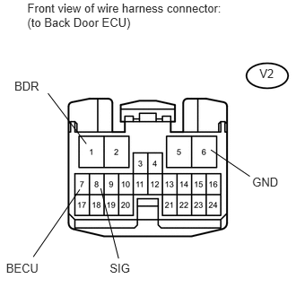
3.CHECK HARNESS AND CONNECTOR (BACK DOOR ECU - BATTERY, IGNITION SWITCH, BODY GROUND)
a.
U154023E01
0.317,0.01 2.646,0.346 2.330,0.336 10 Front view of wire harness connector: (to Back Door ECU) 0.167,0.912 0.499,1.067 0.332,0.156 10 BDR 0.07,3.029 0.474,3.178 0.404,0.149 10 BECU 1.274,3.029 1.545,3.176 0.272,0.147 10 SIG 2.929,2.029 3.270,2.176 0.341,0.147 10 GND 0.557,1.083 1.002,1.67 false 1.17,2.187 1.377,3.001 false 0.386,2.983 0.926,2.2 false 2.901,2.047 2.448,1.74 false 3.013,0.775 3.205,0.926 0.191,0.151 10 V2

Disconnect the V2 back door ECU connector.


b.

Measure the voltage according to the value(s) in the table below.

Standard Voltage:
Tester Connection Switch Condition Specified Condition
V2-1 (BDR) - Body ground Always 11 to 14 V
V2-7 (BECU) - Body ground Always 11 to 14 V
V2-8 (SIG) - Body ground Ignition Switch
OFF → ON
Below 1 V → 11 to 14 V


c.

Measure the resistance according to the value(s) in the table below.

Standard Resistance:
Tester Connection Condition Specified Condition
V2-6 (GND) - Body ground Always Below 1 Ω


d.

Reconnect the back door ECU connector.


OK

4.INSPECT REAR WIPER MOTOR ASSEMBLY

NG

REPAIR OR REPLACE HARNESS OR CONNECTOR

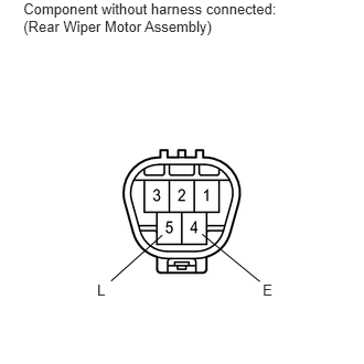
4.INSPECT REAR WIPER MOTOR ASSEMBLY
a.

Remove the rear wiper motor assembly.


E160103E01
0.221,0.001 2.717,0.316 2.496,0.315 10 Component without harness connected: (Rear Wiper Motor Assembly) 2.481,2.653 2.605,2.804 0.123,0.151 10 E 0.917,2.653 1.041,2.809 0.123,0.156 10 L 1.049,2.653 1.533,2.22 false 1.908,2.211 2.453,2.658 false

b.

Connect the battery positive (+) lead to terminal 5 (L) and the negative (-) lead to terminal 4 (E).


c.

Check that the rear wiper motor operates.

OK:

Rear wiper motor operates.


d.

Reinstall the rear wiper motor assembly.


OK

5.CHECK HARNESS AND CONNECTOR (REAR WIPER MOTOR ASSEMBLY - BACK DOOR ECU)

NG

REPLACE REAR WIPER MOTOR ASSEMBLY

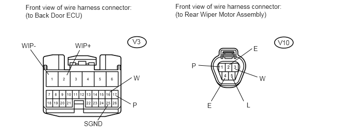
5.CHECK HARNESS AND CONNECTOR (REAR WIPER MOTOR ASSEMBLY - BACK DOOR ECU)
a.

Disconnect the V3 back door ECU connector.
E344986E01
1.031,1.583 0.646,1.052 false 1.417,1.594 1.688,1.063 false 2.323,1.958 2.792,1.646 false 2.458,2.031 2.771,2.208 false 2.292,2.219 2.073,2.552 false 4.771,1.656 4.479,2.146 false 4.917,1.635 5.167,2.146 false 4.99,1.469 5.458,1.635 false 4.667,1.417 4.208,1.385 false 4.865,1.375 5.344,1.031 false 0.542,0.073 2.792,0.438 2.25,0.365 10 false Front view of wire harness connector: (to Back Door ECU) 3.719,0.052 5.958,0.5 2.24,0.448 10 false Front view of wire harness connector: (to Rear Wiper Motor Assembly) 2.813,0.802 3.125,1 0.313,0.198 10 false V3 5.896,0.823 6.354,1.021 0.458,0.198 10 false V10 0.458,0.885 1.073,1.083 0.615,0.198 10 false WIP- 1.594,0.885 2.208,1.083 0.615,0.198 10 false WIP+ 2.833,1.573 2.99,1.771 0.156,0.198 10 false W 2.813,2.146 2.969,2.344 0.156,0.198 10 false P 1.781,2.542 2.396,2.74 0.615,0.198 10 false SGND 5.375,0.948 5.531,1.146 0.156,0.198 10 false E 5.5,1.583 5.656,1.781 0.156,0.198 10 false W 5.229,2.146 5.385,2.344 0.156,0.198 10 false L 4.396,2.156 4.552,2.354 0.156,0.198 10 false E 4.063,1.313 4.219,1.51 0.156,0.198 10 false P


b.

Disconnect the V10 rear wiper motor assembly connector.


c.

Measure the resistance according to the value(s) in the table below.

Standard Resistance:
Tester Connection Condition Specified Condition
V3-1 (WIP-) - V10-4 (E) Always Below 1 Ω
V3-1 (WIP-) or V10-4 (E) - Body ground Always 10 kΩ or higher
V3-2 (WIP+) - V10-5 (L) Always Below 1 Ω
V3-2 (WIP+) or V10-5 (L) - Body ground Always 10 kΩ or higher
V3-16 (W) - V10-3 (W) Always Below 1 Ω
V3-16 (W) or V10-3 (W) - Body ground Always 10 kΩ or higher
V3-17 (P) - V10-1 (P) Always Below 1 Ω
V3-17 (P) or V10-1 (P) - Body ground Always 10 kΩ or higher
V3-25 (SGND) - V10-2 (E) Always Below 1 Ω
V3-25 (SGND) or V10-2 (E) - Body ground Always 10 kΩ or higher


d.

Reconnect the rear wiper motor assembly connector.


e.

Reconnect the back door ECU connector.


OK

REPLACE BACK DOOR ECU

NG

REPAIR OR REPLACE HARNESS OR CONNECTOR