LIGHTING (EXT) LIGHTING SYSTEM Door Mirror Foot Light Circuit
DESCRIPTION
Control of the exterior foot lights is performed by the mirror control ECU, which is installed inside the driver door and turns on/off the puddle light in each door mirror.
The mirror control ECU uses CAN communication to receive signals transmitted from each ECU (the IG SW signal, park shift position signal, driver seat courtesy signal, passenger seat courtesy signal, and door lock/unlock output factor signal) and then controls the illumination of the exterior foot lights.
WIRING DIAGRAM
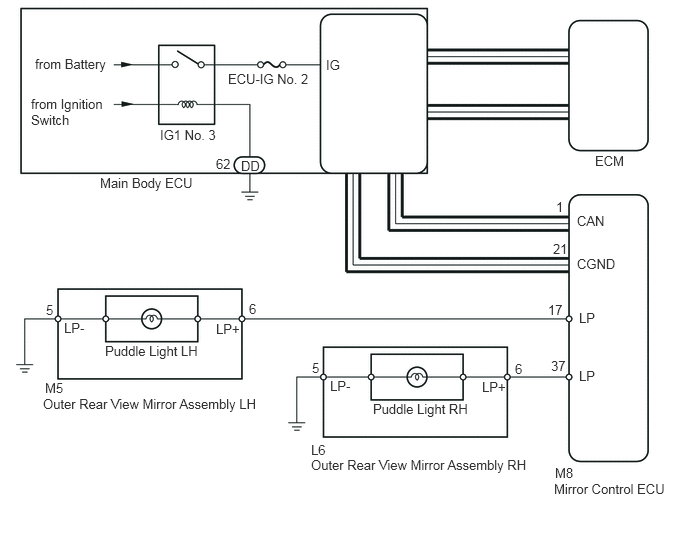
PROCEDURE
Connect the Techstream to the DLC3.
Turn the ignition switch to ON.
Turn the Techstream on.
Enter the following menus: Body Electrical / Mirror ECU / Active Test / Foot Light.
Check that the Puddle light turns on/off.
| Tester Display | Test Part | Control Range | Diagnostic Note |
|---|---|---|---|
| Foot Light | Puddle light | ON or OFF | - |
- OK:
Puddle light turns on/off.
OK
NG
Check for CAN communication system DTCs output.
- OK:
CAN communication system DTCs are not output.
OK
NG
(See pagePower Source / Network>NETWORKING>CAN COMMUNICATION SYSTEM>HOW TO PROCEED WITH TROUBLESHOOTING)
Identify the control system where the problem occurs.
| Result | Proceed to |
|---|---|
| All of the following apply | A |
| When changing the shift position | B |
| When operating the ignition switch | C |
| When opening or closing a door | D |
| When operating a door lock | E |
A
B
C
D
E
Connect the Techstream to the DLC3.
Turn the ignition switch to ON.
Turn the Techstream on.
Enter the following menus: Powertrain / Engine and ECT / Data List / Shift SW Status (P Range)
According to the display on the Techstream, read the Data List.
| Tester Display | Measurement Item/Range | Normal Condition | Diagnostic Note |
|---|---|---|---|
| Shift SW Status (P Range) | PNP switch status/
ON or OFF |
Shift lever is:
·
In P: ON ·
Not in P: OFF |
When shift lever position displayed on Techstream differs from actual position, adjustment of PNP switch or shift cable may be incorrect |
- OK:
The Techstream display changes normally when shift lever is moved.
| Result | Proceed to |
|---|---|
| OK | A |
| NG (for two wheel drive model) | B |
| NG (for four wheel drive model) | C |
A
B
C
Connect the Techstream to the DLC3.
Turn the ignition switch to ON.
Turn the Techstream on.
Enter the following menus: Body Electrical / Main Body / Data List / IG SW.
According to the display on the Techstream, read the Data List.
| Tester Display | Measurement Item/Range | Normal Condition | Diagnostic Note |
|---|---|---|---|
| IG SW | Ignition switch status/
ON or OFF |
Ignition switch is:
·
On: ON ·
Not on ON: OFF |
- |
- OK:
The Techstream display changes normally when ignition switch is operated.
OK
NG
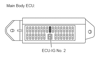
Remove the ECU-IG No. 2 fuse from the main Body ECU.
Measure the resistance according to the value(s) in the table below.
- Standard Resistance:
Tester Connection Condition Specified Condition ECU-IG No. 2 fuse Always Below 1 Ω
Reinstall the ECU-IG No. 2 fuse.
OK
NG
Connect the Techstream to the DLC3.
Turn the ignition switch to ON.
Turn the Techstream on.
Enter the following menus: Body Electrical / Main Body / Data List.
According to the display on the Techstream, read the Data List.
| Tester Display | Measurement Item/Range | Normal Condition | Diagnostic Note |
|---|---|---|---|
| D Door Courtesy SW | Front door courtesy light switch LH signal / ON or OFF | ON: Front door courtesy light switch LH ON
OFF: Front door courtesy light switch LH OFF |
- |
| P Door Courtesy SW | Front door courtesy light switch RH signal / ON or OFF | ON: Front door courtesy light switch RH ON
OFF: Front door courtesy light switch RH OFF |
- |
- OK:
The Techstream display changes normally when door courtesy light switch is operated.
OK
NG
Connect the Techstream to the DLC3.
Turn the ignition switch to ON.
Turn the Techstream on.
Enter the following menus: Body Electrical / Main Body / Data List / D-Door Lock Pos SW.
According to the display on the Techstream, read the Data List.
| Tester Display | Measurement Item/Range | Normal Condition | Diagnostic Note |
|---|---|---|---|
| D-Door Lock Pos SW | Front door lock switch signal / ON or OFF | ON: Front door lock switch ON
OFF: Front door lock switch OFF |
- |
- OK:
The Techstream display changes normally when door lock switch is operated.
OK
NG
(See pageVehicle Interior>DOOR LOCK>POWER DOOR LOCK CONTROL SYSTEM>HOW TO PROCEED WITH TROUBLESHOOTING)
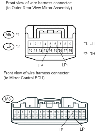
for LH:
Disconnect the M5 outer rear view mirror assembly LH connector.
Disconnect the M8 mirror control ECU connector.
Measure the resistance according to the value(s) in the table below.
- Standard Resistance:
Tester Connection Condition Specified Condition M5-6 (LP+) - M8-17 (LP) Always Below 1 Ω M5-5 (LP-) - Body Ground Always Below 1 Ω M5-6 (LP+) - Body Ground Always 10 kΩ or higher
Reconnect the mirror control ECU connector.
Reconnect the outer rear view mirror assembly LH connector.
for RH:
Disconnect the L6 outer rear view mirror assembly RH connector.
Disconnect the M8 mirror control ECU connector.
Measure the resistance according to the value(s) in the table below.
- Standard Resistance:
Tester Connection Condition Specified Condition L6-6 (LP+) - M8-37 (LP) Always Below 1 Ω L6-5 (LP-) - Body Ground Always Below 1 Ω L6-6 (LP+) - Body Ground Always 10 kΩ or higher
Reconnect the mirror control ECU connector.
Reconnect the outer rear view mirror assembly RH connector.
OK
NG
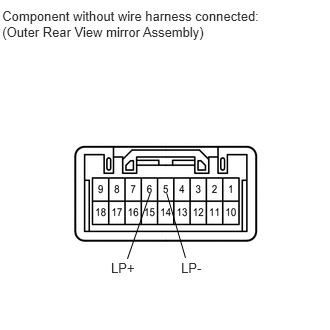
Remove the outer rear view mirror assembly (See page Vehicle Exterior>LIGHTING (EXT)>DOOR MIRROR FOOT LIGHT>REMOVAL).
Apply battery voltage to the terminals and check that the puddle light turn on.
- OK:
Measurement Connection Specified Condition Positive battery (+) → 6 (LP+)
Negative battery (-) → 5 (LP-)Puddle light turn on.
Reinstall the outer rear view mirror assembly.
OK
NG
Temporarily replace the puddle light bulb with a new or normally functioning one (See page Vehicle Exterior>LIGHTING (EXT)>DOOR MIRROR FOOT LIGHT>REMOVAL).
Check that the puddle light turn on.
- OK:
Puddle light turn on.
OK
NG