EXTERIOR PANELS / TRIM FRONT BUMPER DISASSEMBLY
PROCEDURE

 89341B
1.REMOVE NO. 2 ULTRASONIC SENSOR (w/ Intuitive Parking Assist System)
52711A
2.REMOVE FRONT BUMPER GARNISH
Remove the 6 clips.
Detach the 17 claws and remove the front bumper garnish.
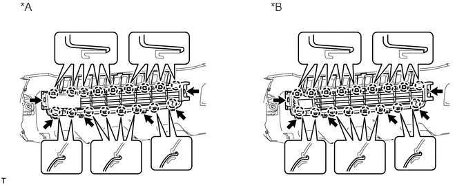
| *A | w/o Dynamic Laser Cruise Control System | *B | w/ Dynamic Laser Cruise Control System |
52717
3.REMOVE FRONT BUMPER MOULDING RETAINER
Remove the 5 screws.
Detach the 6 guides and remove the front bumper moulding retainer.
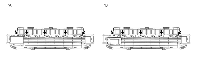
| *A | w/o Dynamic Laser Cruise Control System | *B | w/ Dynamic Laser Cruise Control System |
52129B
4.REMOVE FRONT BUMPER LOWER COVER (w/ Dynamic Laser Cruise Control System)
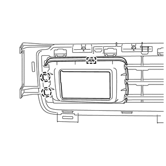
Detach the 2 claws and guide and remove the front bumper lower cover.
81482C
5.REMOVE FOG LIGHT COVER LH
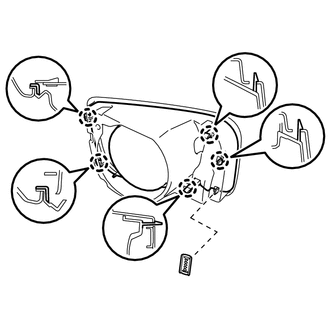
Remove the clip.
Detach the 5 claws and remove the fog light cover LH.
81481E
6.REMOVE FOG LIGHT COVER RH
- HINT:
-
Use the same procedure described for the LH side.
52126A
7.REMOVE FOG LIGHT MOUNTING BRACKET LH (w/ Fog Light)
52125A
8.REMOVE FOG LIGHT MOUNTING BRACKET RH (w/ Fog Light)
- HINT:
-
Use the same procedure described for the LH side.
81220
9.REMOVE FOG LIGHT ASSEMBLY LH (w/ Fog Light)
81210A
10.REMOVE FOG LIGHT ASSEMBLY RH (w/ Fog Light)
- HINT:
-
Use the same procedure described for the LH side.
53878M
11.REMOVE FRONT FENDER LINER BRACKET LH
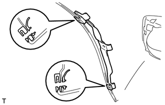
Detach the 2 claws and remove the front fender liner bracket LH.
53877E
12.REMOVE FRONT FENDER LINER BRACKET RH
- HINT:
-
Use the same procedure described for the LH side.
13.REMOVE CLIP
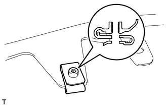
Remove the clip.
- HINT:
-
Use the same procedure for all clips.
52116A
14.REMOVE FRONT BUMPER SIDE SUPPORT LH
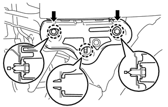
Remove the 2 screws.
Detach the 3 claws and remove the front bumper side support LH.
52115A
15.REMOVE FRONT BUMPER SIDE SUPPORT RH
- HINT:
-
Use the same procedure described for the LH side.
52503B
16.REMOVE FRONT UPPER CENTER BUMPER RETAINER
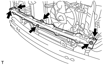
Remove the 6 nuts and front upper center bumper retainer.
52538
17.REMOVE FRONT BUMPER END RETAINER LH
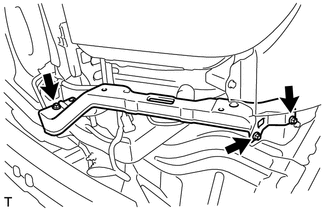
Remove the 3 nuts and front bumper end retainer LH.
52537
18.REMOVE FRONT BUMPER END RETAINER RH
- HINT:
-
Use the same procedure described for the LH side.
88211A
19.REMOVE LASER RADAR SENSOR (w/ Dynamic Laser Cruise Control System)
52131A
20.REMOVE FRONT BUMPER REINFORCEMENT
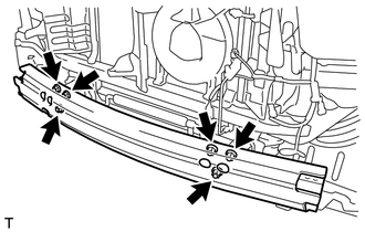
Remove the 6 nuts and front bumper reinforcement.
52143B
21.REMOVE FRONT BUMPER SIDE BRACKET
- HINT:
-
Use the same procedure for both front bumper side brackets.
Put a 7 mm (0.276 in.) drill bit into a drill.
Wind tape around the drill bit approximately 5 mm (0.197 in.) from the tip of the drill as shown in the illustration.
- HINT:
-
Tape the 7 mm (0.276 in.) drill bit to prevent the drill bit from going too deep.
Lightly press the drill against the 3 rivets and drill off the flanges of the 3 rivets.
- CAUTION:
-
Be careful of the drilled rivet as it may become hot.
- NOTICE:
- ·
Pressing the drill too firmly will cause the rivet to turn and result in the rivet not being drilled through.
·Do not pry the rivet with the drill because this may cause damage to the installation holes of the rivet or the drill bit.
Remove the front bumper side bracket.
Using a vacuum cleaner, remove the rivet fragments and shavings from the drilled area.
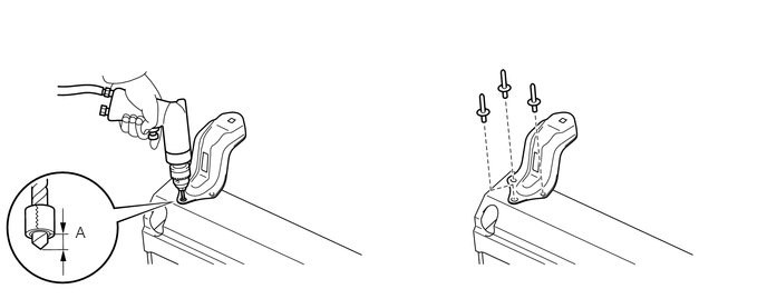
- Standard:
Area Specified Condition A 5 mm (0.197 in.)
52026B
22.REMOVE FRONT NO. 2 BUMPER EXTENSION SUB-ASSEMBLY LH
Remove the 4 nuts and front No. 2 bumper extension sub-assembly LH.
- HINT:
-
The front No. 2 bumper extension cannot be removed easily if the stud bolts on the back side are installed to the body.
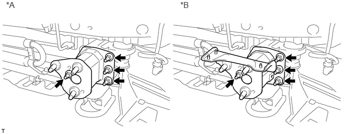
| *A | w/o Dynamic Laser Cruise Control System | *B | w/ Dynamic Laser Cruise Control System |
52025B
23.REMOVE FRONT NO. 2 BUMPER EXTENSION SUB-ASSEMBLY RH
- HINT:
-
Use the same procedure described for the LH side.
53294C
24.REMOVE RADIATOR SIDE DEFLECTOR LH
53293C
25.REMOVE RADIATOR SIDE DEFLECTOR RH