EXTERIOR PANELS / TRIM FRONT BUMPER REASSEMBLY
PROCEDURE

 53294C
1.INSTALL RADIATOR SIDE DEFLECTOR LH
53293C
2.INSTALL RADIATOR SIDE DEFLECTOR RH
52026B
3.INSTALL FRONT NO. 2 BUMPER EXTENSION SUB-ASSEMBLY LH
Install the front No. 2 bumper extension sub-assembly LH with 4 new nuts.
- Torque:
- 58 N*m (591 kgf*cm, 43 ft.*lbf)
52025B
4.INSTALL FRONT NO. 2 BUMPER EXTENSION SUB-ASSEMBLY RH
- HINT:
-
Use the same procedure described for the LH side.
52143B
5.INSTALL FRONT BUMPER SIDE BRACKET
- HINT:
-
Use the same procedure for both front bumper side brackets.
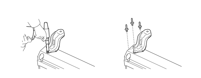
Install the front bumper side bracket.
Install a nose piece to an air riveter or hand riveter.
Insert the mandrel part of a new rivet into the nose piece.
Place the riveter upright against the front bumper side bracket and install the 3 rivets.
- HINT:
-
If the rivet cannot be cut, pull it once and cut it.
- NOTICE:
- ·
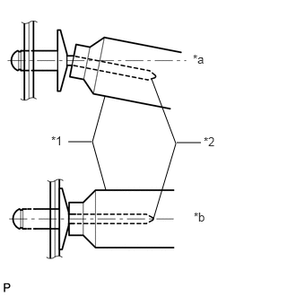 1.219,1.115 1.073,1.646 1.073,1.646 1.229,2.208 false 1.063,1.646 0.792,1.646 false 1.76,0.917 2.042,1.667 2.042,1.667 1.781,2.542 false 2.052,1.656 2.333,1.656 false 2.24,0.604 2.438,0.802 0.198,0.198 10 false *a 2.25,2.438 2.469,2.635 0.219,0.198 10 false *b 0.594,1.552 0.781,1.75 0.188,0.198 10 false *1 2.365,1.563 2.552,1.74 0.188,0.177 10 false *2
Do not pry the rivet with the riveter as this will cause damage to the riveter and mandrel.
Text in Illustration *1 Riveter *2 Mandrel *a INCORRECT *b CORRECT
·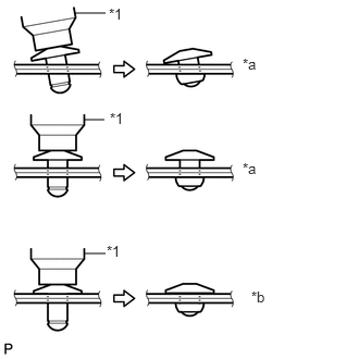 0.708,0.125 1.01,0.125 false 0.802,1.146 1,1.146 false 0.813,2.427 1.01,2.427 false 2.323,0.531 2.51,0.708 0.188,0.177 10 false *a 2.323,1.531 2.5,1.708 0.177,0.177 10 false *a 2.406,2.76 2.604,2.938 0.198,0.177 10 false *b 1.021,2.323 1.198,2.479 0.177,0.156 10 false *1 1.052,1.052 1.229,1.208 0.177,0.156 10 false *1 1.042,0.052 1.219,0.208 0.177,0.156 10 false *1
Confirm that the rivets are seated properly against the front bumper side bracket.
·Do not tilt the riveter when installing the rivet to the front bumper side bracket.
·Do not leave any space between the rivet head and front bumper side bracket.
Text in Illustration *1 Riveter *a INCORRECT *b CORRECT
·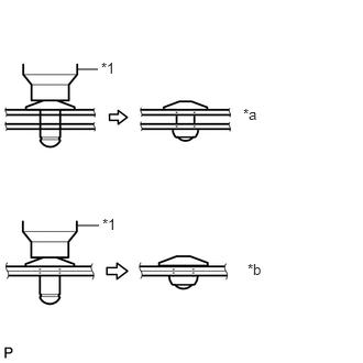 0.729,0.656 0.927,0.656 false 0.729,2.135 0.938,2.135 false 2.302,1 2.5,1.177 0.198,0.177 10 false *a 2.344,2.469 2.552,2.646 0.208,0.177 10 false *b 0.958,0.563 1.156,0.729 0.198,0.167 10 false *1 0.969,2.042 1.177,2.208 0.208,0.167 10 false *1
Do not leave any space between the front bumper side bracket and front door panel. Firmly hold together the 2 items while installing the rivet.
Text in Illustration *1 Riveter *a INCORRECT *b CORRECT
52131A
6.INSTALL FRONT BUMPER REINFORCEMENT
Install the front bumper reinforcement with 6 new nuts.
- Torque:
- 71 N*m (724 kgf*cm, 52 ft.*lbf)
88211A
7.INSTALL LASER RADAR SENSOR (w/ Dynamic Laser Cruise Control System)
52538
8.INSTALL FRONT BUMPER END RETAINER LH
Install the front bumper end retainer LH with 3 new nuts.
- Torque:
- 5.4 N*m (55 kgf*cm, 48 in.*lbf)
52537
9.INSTALL FRONT BUMPER END RETAINER RH
- HINT:
-
Use the same procedure described for the LH side.
52503B
10.INSTALL FRONT UPPER CENTER BUMPER RETAINER
Install the front upper center bumper retainer with 6 new nuts.
- Torque:
- 5.4 N*m (55 kgf*cm, 48 in.*lbf)
52116A
11.INSTALL FRONT BUMPER SIDE SUPPORT LH
Attach the 3 claws to install the front bumper side support LH.
Install the 2 screws.
52115A
12.INSTALL FRONT BUMPER SIDE SUPPORT RH
- HINT:
-
Use the same procedure described for the LH side.
13.INSTALL CLIP
Install the clip.
- HINT:
-
Use the same procedure for all clips.
53878M
14.INSTALL FRONT FENDER LINER BRACKET LH
Attach the 2 claws to install the front fender liner bracket LH.
53877E
15.INSTALL FRONT FENDER LINER BRACKET RH
- HINT:
-
Use the same procedure described for the LH side.
81220
16.INSTALL FOG LIGHT ASSEMBLY LH (w/ Fog Light)
81210A
17.INSTALL FOG LIGHT ASSEMBLY RH (w/ Fog Light)
- HINT:
-
Use the same procedure described for the LH side.
52126A
18.INSTALL FOG LIGHT MOUNTING BRACKET LH (w/ Fog Light)
52125A
19.INSTALL FOG LIGHT MOUNTING BRACKET RH (w/ Fog Light)
- HINT:
-
Use the same procedure described for the LH side.
81482C
20.INSTALL FOG LIGHT COVER LH
Attach the 5 claws to install the fog light cover LH.
Install the clip.
81481E
21.INSTALL FOG LIGHT COVER RH
- HINT:
-
Use the same procedure described for the LH side.
52129B
22.INSTALL FRONT BUMPER LOWER COVER (w/ Dynamic Laser Cruise Control System)
Attach the 2 claws and guide to install the front bumper lower cover.
52717
23.INSTALL FRONT BUMPER MOULDING RETAINER
Attach the 6 guides to install the front bumper moulding retainer.
Install the 5 screws.
52711A
24.INSTALL FRONT BUMPER GARNISH
Attach the 17 claws to install the front bumper garnish.
Install the 6 clips.
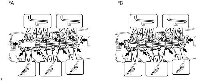
| *A | w/o Dynamic Laser Cruise Control System | *B | w/ Dynamic Laser Cruise Control System |
89341B
25.INSTALL NO. 2 ULTRASONIC SENSOR (w/ Intuitive Parking Assist System)