8HP51 AUTOMATIC TRANSMISSION / TRANSAXLE TRANSMISSION VALVE BODY REMOVAL
PROCEDURE

 1.DISCONNECT CABLE FROM NEGATIVE BATTERY TERMINAL (for B48)
Click hereGeneral>MAINTENANCE>B48 BATTERY>REMOVAL
2.DISCONNECT CABLE FROM NEGATIVE BATTERY TERMINAL (for B58)
Click hereGeneral>MAINTENANCE>B58 BATTERY>REMOVAL
50819
3.REMOVE FRONT FLOOR COVER
4.REMOVE TRANSMISSION OIL SUMP
- CAUTION:
- ·
Materials harmful to health.
Contact with fluids harmful to health!
-Note and follow safety information on containers.
-Conduct all work in appropriate personal protective equipment only.
- NOTICE:
- ·
Damage to the transmission oil sump.
Non-observance of the automatic transmission fluid specifications may lead to severe damage to the automatic transmission.
-Remove transmission oil sump only after it has cooled down.
-Use only the approved Automatic Gearbox Oil ATF 3+.
-After completion of repair work, check automatic transmission fluid level.
- HINT:
-
Collect and dispose of emerging fluids. Observe country-specific waste disposal regulations.
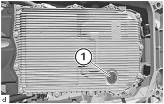
Release oil drain plug (1).
- HINT:
-
Drain, catch and dispose of the automatic transmission fluid.
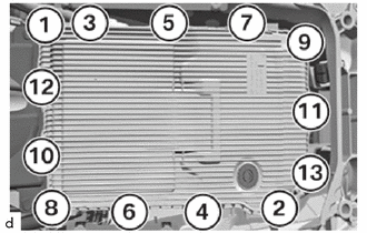
Loosen the T40 bolts (1) to (13).
Remove transmission oil sump.
5.REMOVE HYDRAULIC IMPULSE STORAGE
6.REMOVE MECHATRONICS
- CAUTION:
- ·
Materials harmful to health.
Contact with fluids harmful to health!
-Note and follow safety information on containers.
-Conduct all work in appropriate personal protective equipment only.
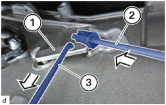
Pull the selector shaft journal (1) downward with the special tool 2 355 850 (3) in the direction of the arrow.
- SST
- 09700-WA050
Install the special tool 2 355 850 (2) between the selector shaft journal (1) and transmission housing in direction of arrow.
- SST
- 09700-WA050
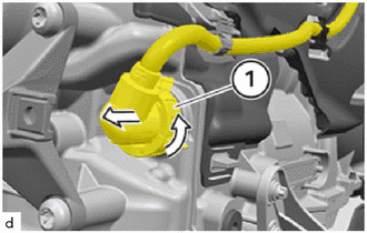
Turn the connector (1) in the direction of the arrow and pull it off.
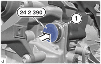
Insert special tool 0 494 213 (24 2 390) in sealing sleeve (1).
- SST
- 09300-WA100
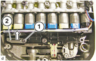
Unscrew the T40 bolt (1) and unlock the sealing sleeve with the slide(2).
Press the slide (2) in the direction of the arrow.
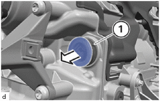
Remove the sealing sleeve (1) with the special tool 0 494 213 (24 2 390).
- SST
- 09300-WA100
- HINT:
-
The sealing sleeve (1) must be installed in the same mounting orientation.
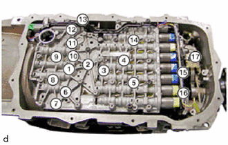
Release the T40 bolts (4) and (9) from the mechatronics.
- HINT:
-
Do not release the remaining the T40 bolts (1) to (3), (5) to (8) and (10) to (17) yet.
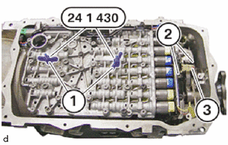
Install special tool 0 496 715 (24 1 430).
- SST
- 09300-WA080
Tighten the wing nuts (1).
Loosen the T40 bolts (2).
Carefully pull the output speed sensor (3) out of the housing and insert it in the recess on the module.
- NOTICE:
-
The journal on the output speed sensor may break off during removal or installation.
- HINT:
- ·
Note the original mounting orientation of the output speed sensor.
·Observe the correct mounting orientation when installing the output speed sensor.
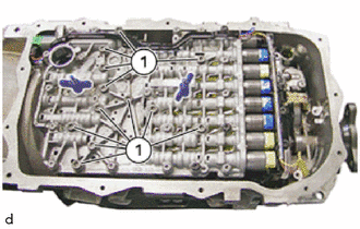
Loosen the T40 bolts (1).
Release the wing nuts on the special tool 0 496 715 (24 1 430).
- SST
- 09300-WA080
Remove mechatronics.
- HINT:
-
Carefully remove mechatronics.
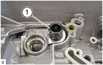
Remove pressure pipe (1).