METER / GAUGE / DISPLAY COMBINATION METER REMOVAL
CAUTION / NOTICE / HINT
- CAUTION:
- ·
Working on 12 V vehicle electrical system.
Risk of short circuits! Risk of fire!
-Detach the cable from the negative (-) battery terminal.
- NOTICE:
- ·
Electrostatic discharge.
Damage to or destruction of electrical components.
-Leave electrical components in original packaging until just before they are installed. Use the original packaging only for any return shipments. Always package removed components straight away.
-Only touch the housings of electrical components. Do not touch pins or multi-pin connectors directly.
-Antistatic work clothing and antistatic shoes (with ESD symbol).
-For additional information see:
Click hereGeneral>INTRODUCTION>REPAIR INSTRUCTION>PRECAUTION
·Before performing work on electronic components, disconnect the cable from the negative (-) battery terminal to prevent damage to the electrical system or components.
·When disconnecting the cable, turn the START-STOP button (engine switch) and headlight switch off and loosen the cable nut completely. Perform these operations without twisting or prying on the cable. Then disconnect the cable.
·Clock settings, radio settings, audio system memory, DTCs and other data will be cleared when the cable is disconnected from the negative (-) battery terminal. Write down any necessary data before disconnecting the cable.
- HINT:
- ·
Combination meter assembly must be programed after it is replaced.
For additional information see:
Click hereGeneral>INTRODUCTION>REPAIR INSTRUCTION>PRECAUTION
·Use the same procedure for LHD and RHD vehicles.
·The following procedure is for LHD vehicles.
PROCEDURE

 1.DISCONNECT CABLE FROM NEGATIVE BATTERY TERMINAL
for B48:
Click hereGeneral>MAINTENANCE>B48 BATTERY>REMOVAL
for B58:
Click hereGeneral>MAINTENANCE>B58 BATTERY>REMOVAL
2.ADJUST THE STEERING COLUMN POSITION
Adjust the length of the steering column to the maximum length.
Move the steering column to the lowest steering column position.
3.REMOVE COMBINATION METER ASSEMBLY
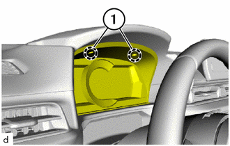
Loosen T20 screws (1).
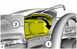

|
Rotate |

|
Protective Tape |
Apply protective tape as shown in the illustration.
Using a molding remover A, rotate the combination meter assembly (2) forward in direction of arrow.
Detach the retaining tabs (1) to pull the combination meter assembly (2) forward.
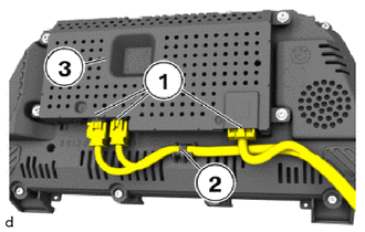
Unlock and disconnect plug connections (1).
Detach wiring harness from the holder (2).
Removing the combination meter assembly (3).