METER / GAUGE / DISPLAY HEADUP DISPLAY REMOVAL
CAUTION / NOTICE / HINT
- CAUTION:
- ·
Working on 12 V vehicle electrical system.
Risk of short circuits! Risk of fire!
-Detach the cable from the negative (-) battery terminal.
·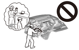
Pyrotechnic components.
Danger! Life-threatening injuries!
-All work on pyrotechnic parts may be carried out by technically experienced and appropriately trained personnel only.
-Some of these service operations affect the SRS airbag system. Read the precautionary notices concerning the SRS airbag system before servicing.
-Replace any damaged part or ones that have been dropped.
-For additional information see:
Click hereVehicle Interior>SUPPLEMENTAL RESTRAINT SYSTEMS>AIRBAG SYSTEM>PRECAUTION
- NOTICE:
- ·
Electrostatic discharge.
Damage to or destruction of electrical components.
-Leave electrical components in original packaging until just before they are installed. Use the original packaging only for any return shipments. Always package removed components straight away.
-Only touch the housings of electrical components. Do not touch pins or multi-pin connectors directly.
-Antistatic work clothing and antistatic shoes (with ESD symbol).
-For additional information see:
Click hereGeneral>INTRODUCTION>REPAIR INSTRUCTION>PRECAUTION
·Before performing work on electronic components, disconnect the cable from the negative (-) battery terminal to prevent damage to the electrical system or components.
·When disconnecting the cable, turn the START-STOP button (engine switch) and headlight switch off and loosen the cable nut completely. Perform these operations without twisting or prying on the cable. Then disconnect the cable.
·Clock settings, radio settings, audio system memory, DTCs and other data will be cleared when the cable is disconnected from the negative (-) battery terminal. Write down any necessary data before disconnecting the cable.
- HINT:
- ·
Meter mirror sub-assembly must be programed after it is replaced.
For additional information see:
Click hereGeneral>INTRODUCTION>REPAIR INSTRUCTION>PRECAUTION
·Use the same procedure for LHD and RHD vehicles.
·The following procedure is for LHD vehicles.
PROCEDURE

 1.REMOVE INSTRUMENT PANEL SAFETY PAD ASSEMBLY
55468C
2.REMOVE NO. 1 INSTRUMENT CLUSTER FINISH PANEL SEAL
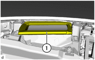
Remove the No. 1 instrument cluster finish panel seal (1).
83108
3.REMOVE METER MIRROR SUB-ASSEMBLY
- NOTICE:
- ·
Electrostatic discharge.
Damage to or destruction of electrical components.
-Leave electrical components in original packaging until just before they are installed. Use the original packaging only for any return shipments. Always package removed components straight away.
-Only touch the housings of electrical components. Do not touch pins or multi-pin connectors directly.
-Antistatic work clothing and antistatic shoes (with ESD symbol).
-For additional information see:
Click hereGeneral>INTRODUCTION>REPAIR INSTRUCTION>PRECAUTION
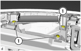
Remove the T30 bolts (1).
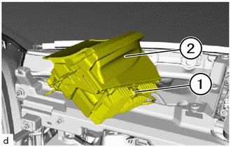
Feed out meter mirror sub-assembly (2) from instrument panel reinforcement sub-assembly.
Unlock plug connection (1) and disconnect.
Remove the meter mirror sub-assembly (2).