INTERIOR PANELS / TRIM INSTRUMENT PANEL SAFETY PAD REMOVAL
CAUTION / NOTICE / HINT
- CAUTION:
- ·
Working on 12 V vehicle electrical system.
Risk of short circuits! Risk of fire!
-Detach the cable from the negative (-) battery terminal.
- ·
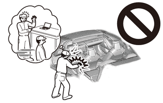
Pyrotechnic components.
Danger! Life-threatening injuries!
-All work on pyrotechnic parts may be carried out by technically experienced and appropriately trained personnel only.
-Some of these service operations affect the SRS airbag system. Read the precautionary notices concerning the SRS airbag system before servicing.
-Replace any damaged part or ones that have been dropped.
-For additional information see:
Click hereVehicle Interior>SUPPLEMENTAL RESTRAINT SYSTEMS>AIRBAG SYSTEM>PRECAUTION
- NOTICE:
- ·
Electrostatic discharge.
Damage to or destruction of electrical components.
-Leave electrical components in original packaging until just before they are installed. Use the original packaging only for any return shipments. Always package removed components straight away.
-Only touch the housings of electrical components. Do not touch pins or multi-pin connectors directly.
-Antistatic work clothing and antistatic shoes (with ESD symbol).
-For additional information see:
Click hereGeneral>INTRODUCTION>REPAIR INSTRUCTION>PRECAUTION
·Before performing work on electronic components, disconnect the cable from the negative (-) battery terminal to prevent damage to the electrical system or components.
·When disconnecting the cable, turn the START-STOP button (engine switch) and headlight switch off and loosen the cable nut completely. Perform these operations without twisting or prying on the cable. Then disconnect the cable.
·Clock settings, radio settings, audio system memory, DTCs and other data will be cleared when the cable is disconnected from the negative (-) battery terminal. Write down any necessary data before disconnecting the cable.
- HINT:
- ·
Use the same procedure for LHD and RHD vehicles.
·The following procedure is for LHD vehicles.
PROCEDURE

 58801D
1.REMOVE CONSOLE BOX ASSEMBLY
84310
2.REMOVE TURN SIGNAL SWITCH ASSEMBLY
67914
3.REMOVE FRONT DOOR SCUFF PLATE LH
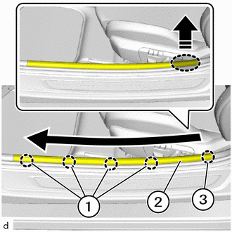

|
Place Hands Here |

|
Order of Removal |

|
Remove in this Direction |
Detach the guide (3) and clips (1) in the order as shown in the illustration.
Remove the front door scuff plate LH (2).
- HINT:
-
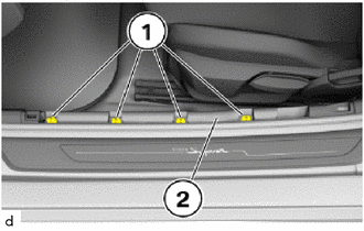
-
If necessary, remove the clips (1) from the floor panel (2) and attach to the front door scuff plate LH.
67913
4.REMOVE FRONT DOOR SCUFF PLATE RH
- HINT:
-
Use the same procedure as for the LH side.
62112A
5.REMOVE COWL SIDE TRIM SUB-ASSEMBLY LH
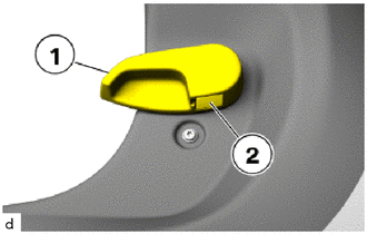
Pull the hood lock release lever protector (1) towards the rear.
Remove the locking wedge (2).
Remove the hood lock release lever protector (1).
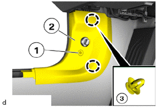
Loosen T20 screw (1).
Detach the clips (3) to remove the cowl side trim sub-assembly LH (2).
62111C
6.REMOVE COWL SIDE TRIM BOARD RH
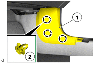
Detach the clips (2) to remove the cowl side trim board RH (1).
55318F
7.REMOVE NO. 2 INSTRUMENT SIDE PANEL

|
Protective Tape |
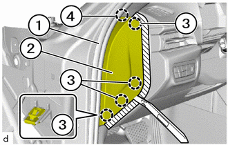
Separate the front door opening trim weatherstrip LH (1) from the area of the No. 2 instrument side panel (2).
Apply protective tape as shown in the illustration.
Using a molding remover A, detach the clips (3).
Detach the guide (4) to remove the No. 2 instrument side panel (2).
55317E
8.REMOVE NO. 1 INSTRUMENT SIDE PANEL
- HINT:
-
Use the same procedure as for the No. 2 side.
Separate the front door opening trim weatherstrip RH from the area of the No. 1 instrument side panel.
Apply protective tape.
Using a molding remover A, detach the clips.
Detach the guide to remove the No. 1 instrument side panel.
w/ Airbag Cut Off Switch:
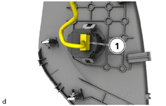
Unlock plug connection (1) and disconnect.
9.REMOVE COMBINATION METER ASSEMBLY
55403F
10.REMOVE INSTRUMENT PANEL FINISH PANEL SUB-ASSEMBLY
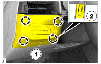
Detach the clips (2) to remove the instrument panel finish panel sub-assembly (1).
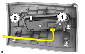
Unlock and disconnect the plug connection (1).
Remove the instrument panel finish panel sub-assembly (2).
55011A
11.REMOVE NO. 1 INSTRUMENT PANEL GARNISH SUB-ASSEMBLY
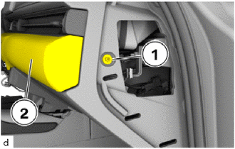
Loosen T20 screw (1) on the No. 1 instrument panel garnish sub-assembly (2).
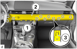
Loosen T20 screw (1).
Detach the clips (3) to remove the No. 1 instrument panel garnish sub-assembly (2).
Pull the No. 1 instrument panel garnish sub-assembly (2) from the instrument panel safety pad assembly slightly forward.
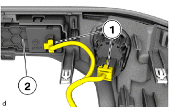
Unlock and disconnect plug connections (1).
Remove the No. 1 instrument panel garnish sub-assembly (2).
12.REMOVE GLOVE COMPARTMENT DOOR LOCK CYLINDER ASSEMBLY
- HINT:
-
Perform this procedure only when replacement of the glove compartment door lock cylinder assembly is necessary.
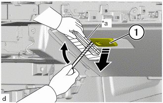
| *a | Wooden Block |
|
|
Protective Tape |
|
|
Apply Pressure in this Direction |
|
|
Remove in this Direction |
Apply protective tape to the glove compartment door assembly as shown in the illustration.
Insert a screwdriver with its blade wrapped in protective tape into the gap between the opener (1) and the glove compartment door assembly.
Using a wooden block as a fulcrum, apply pressure in the direction shown by the arrow in the illustration to break the opener (1) and remove it.
- NOTICE:
-
Make sure the glove compartment door assembly is not damaged in the process.
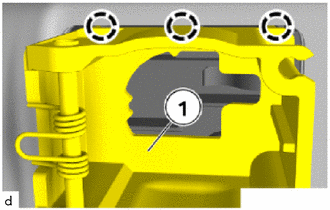
Unclip the housing (1) with a flat screwdriver in the marked areas and remove.
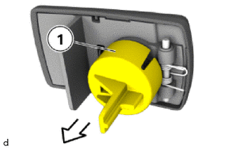

|
Remove in this Direction |
Remove the operating lever (1) in the direction of the arrow.
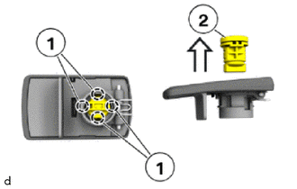
|
|
Remove in this Direction |
Detach retaining lugs (1) and remove the glove compartment door lock cylinder assembly (2) in direction of arrow.
55550
13.REMOVE GLOVE COMPARTMENT DOOR ASSEMBLY
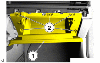
Open the glove compartment door assembly (1).
Loosen T20 screws (2).
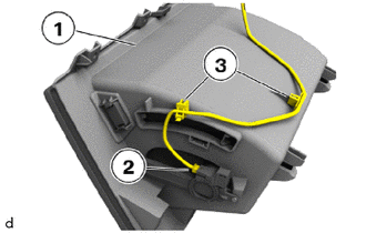
Pull the glove compartment door assembly (1) out slightly and unlock and disconnect the plug connection (2).
Detach the clips (3) of the wiring harness.
w/ Glove Box Light:
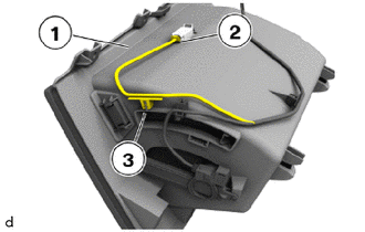
Unlock and disconnect plug connection (2).
Detach the clip (3) of the wiring harness.
Remove the glove compartment door assembly (1).
55650
14.REMOVE NO. 1 INSTRUMENT PANEL REGISTER ASSEMBLY
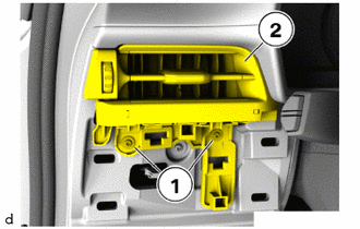
Loosen T20 screws (1) on the No. 1 instrument panel register assembly (2).
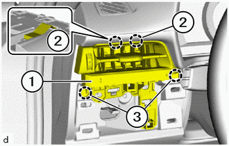
Detach the clips (2) and guides (3) to remove the No. 1 instrument panel register assembly (1).
55660
15.REMOVE NO. 2 INSTRUMENT PANEL REGISTER ASSEMBLY
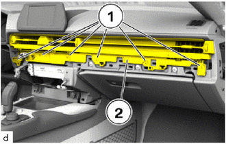
Loosen T20 screws (1) on the No. 2 instrument panel register assembly (2).
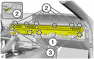
Detach the clips (2) and guides (3).
Pull the No. 2 instrument panel register assembly (1) slightly forward.
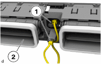
Unlock and disconnect plug connections (1).
Remove the No. 2 instrument panel register assembly (2).
62212
16.REMOVE FRONT PILLAR GARNISH LH
- CAUTION:
- ·
Airbag unit.
Danger! Life-threatening injuries!
-Before performing any work on the airbag, always disconnect the battery earth lead from the battery.
-All work on pyrotechnic parts may be carried out by technically experienced and appropriately trained personnel only.
-Replace any damaged part or ones that have been dropped.
-For additional information see:
Click hereVehicle Interior>SUPPLEMENTAL RESTRAINT SYSTEMS>AIRBAG SYSTEM>PRECAUTION
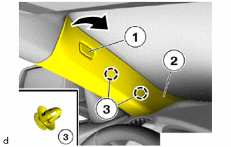
|
|
Pull up |
Remove the front pillar garnish cover LH (1) and loosen T25 screw below it.
Pull up the front pillar garnish LH (2) to detach the clips (3).
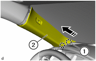
|
|
Remove in this Direction |
Detach the guides (1) to remove the front pillar garnish LH (2) in the direction of the arrow.
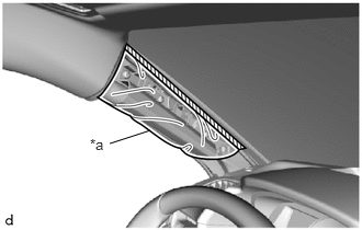
| *a | Protective Cover |
|
|
Adhesive Tape |
Protect the curtain shield airbag assembly.
Completely cover the curtain shield airbag assembly with a cloth or nylon sheet and secure the ends of the cover with adhesive tape as shown in the illustration.
- NOTICE:
-
Cover the curtain shield airbag assembly with a protective cover as soon as the front pillar garnish LH is removed.
62211
17.REMOVE FRONT PILLAR GARNISH RH
- HINT:
-
Use the same procedure as for the LH side.
55422C
18.REMOVE INSTRUMENT CLUSTER FINISH CENTER UPPER PANEL
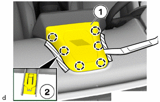
|
|
Protective Tape |
Apply protective tape as shown in the illustration.
Using a molding remover A, detach the clips (2) to remove the instrument cluster finish center upper panel (1).
86160L
19.REMOVE FRONT NO. 4 SPEAKER ASSEMBLY (w/ Front Center Speaker)
86160J
20.REMOVE FRONT NO. 3 SPEAKER ASSEMBLY (w/ Front Center Speaker)
86110B
21.REMOVE MULTI-DISPLAY ASSEMBLY
45286
22.REMOVE STEERING COLUMN COVER
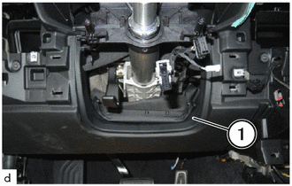
Remove the steering column cover (1).
55414A
23.REMOVE INSTRUMENT CLUSTER FINISH END PANEL (w/ Headup Display)
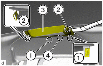
|
|
Protective Tape |
Apply protective tape as shown in the illustration.
Using a molding remover A, detach the clips (2), clips (1) and guide (4) to remove the instrument cluster finish end panel (3).
24.REMOVE INSTRUMENT PANEL SAFETY PAD ASSEMBLY
Instrument panel passenger airbag assembly for Single Type:
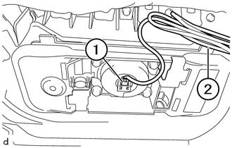
Unlock and disconnect the plug connection (1) and detach the clip (2).
Instrument panel passenger airbag assembly for Dual Type:
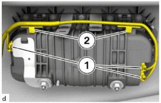
Unlock and disconnect the plug connections (1) and detach the clips (2).
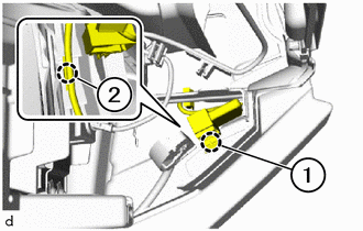
Detach the clips (1) and clips (2) of wiring harness.
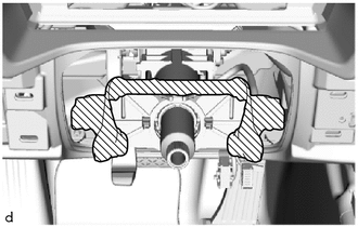
|
|
Protective Tape |
Apply protective tape as shown in the illustration.
Loosen T20 screws (3).
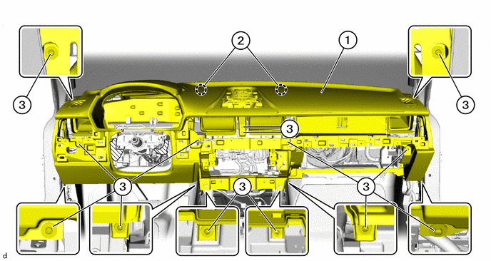
|
|
Protective Tape | - | - |
Detach the guides (2) to remove the instrument panel safety pad assembly (1).
69065A
25.REMOVE AIRBAG CUT OFF SWITCH CYLINDER SUB-ASSEMBLY (w/ Airbag Cut Off Switch)
- HINT:
-
Perform this procedure only when replacement of the instrument side panel is necessary.
-
Click hereVehicle Interior>SUPPLEMENTAL RESTRAINT SYSTEMS>AIRBAG CUT-OFF SWITCH>REMOVAL
84110
26.REMOVE NO. 1 LIGHT CONTROL SWITCH ASSEMBLY
- HINT:
-
Perform this procedure only when replacement of the instrument panel finish panel sub-assembly is necessary.
-
Click hereVehicle Interior>INTERIOR PANELS / TRIM>COMBINATION SWITCH (for Instrument Panel)>REMOVAL
86120A
27.REMOVE RADIO RECEIVER SWITCH KNOB
- HINT:
-
Perform this procedure only when replacement of the No. 1 instrument panel garnish sub-assembly is necessary.
-
Click hereAudio / Visual / Telematics>AUDIO / VIDEO>CONTROL PANEL>REMOVAL
89611
28.REMOVE PUSH START SWITCH
- HINT:
-
Perform this procedure only when replacement of the No. 1 instrument panel garnish sub-assembly is necessary.
- ·
for B48:
Click hereEngine / Hybrid System>B48 (STARTING)>ENGINE SWITCH>REMOVAL
·for B58:
Click hereEngine / Hybrid System>B58 (STARTING)>ENGINE SWITCH>REMOVAL
55054
29.REMOVE GLOVE COMPARTMENT DOOR STOPPER SUB-ASSEMBLY
- HINT:
-
Perform this procedure only when replacement of the glove compartment door stopper sub-assembly is necessary.
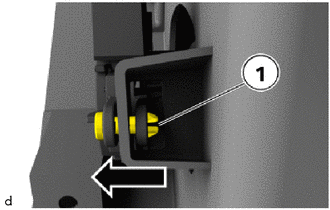
|
|
Remove in this Direction |
Remove the locking pin (1) in the direction of the arrow.
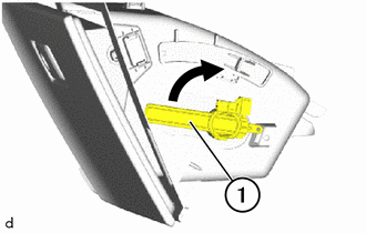
|
|
Turn in this Direction |
Open the glove compartment door assembly slightly.
Turn the glove compartment door stopper sub-assembly (1) clockwise approximately 90° and remove it.
84330
30.REMOVE HAZARD WARNING SIGNAL SWITCH ASSEMBLY
- HINT:
-
Perform this procedure only when replacement of the No. 2 instrument panel register assembly is necessary.
-
Click hereVehicle Exterior>LIGHTING (EXT)>HAZARD WARNING SWITCH>REMOVAL
55962
31.REMOVE NO. 2 SIDE DEFROSTER NOZZLE
- HINT:
-
Perform this procedure only when replacement of the No. 2 side defroster nozzle is necessary.
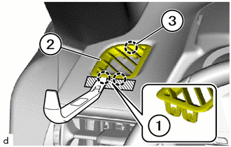
|
|
Protective Tape |
Apply protective tape as shown in the illustration.
Using a molding remover A, detach the claws (1).
Detach the guide (3) to remove the No. 2 side defroster nozzle (2).
55961
32.REMOVE NO. 1 SIDE DEFROSTER NOZZLE
- HINT:
-
Use the same procedure as for the No. 2 side.
33.REMOVE GLOVE BOX LIGHT (w/ Glove Box Light)
- HINT:
-
Perform this procedure only when replacement of the glove compartment door assembly is necessary.
-
Click hereVehicle Interior>LIGHTING (INT)>GLOVE BOX LIGHT>REMOVAL
55317
34.REMOVE INSTRUMENT PANEL PATCH
- HINT:
- ·
Perform this procedure only when replacement of the instrument panel patch is necessary.
·Use the same procedures for the opposite side.
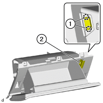
Detach the claws (1) to remove the instrument panel patch (2).
67912A
35.REMOVE FRONT DOOR SCUFF PLATE OUTSIDE LH
- HINT:
-
Perform this procedure only when replacement of the front door scuff plate outside LH is necessary.
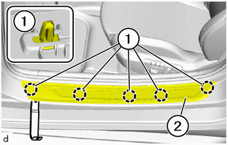
Using a molding remover B, detach the clips (1) to remove the front door scuff plate outside LH (2).
- HINT:
-
-
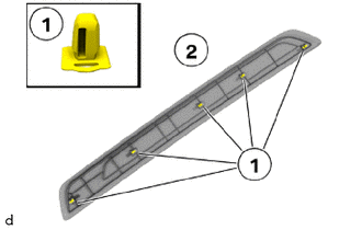
If necessary, remove the clips (1) remaining in the body and mount them on the front door scuff plate outside LH (2).
67911B
36.REMOVE FRONT DOOR SCUFF PLATE OUTSIDE RH
- HINT:
-
Use the same procedure as for the LH side.