INTERIOR PANELS / TRIM INSTRUMENT PANEL SAFETY PAD INSTALLATION
CAUTION / NOTICE / HINT
- HINT:
- ·
Use the same procedure for LHD and RHD vehicles.
·The following procedure is for LHD vehicles.
PROCEDURE

 67912A
1.INSTALL FRONT DOOR SCUFF PLATE OUTSIDE LH
- HINT:
-
Perform this procedure only when replacement of the front door scuff plate outside LH is necessary.
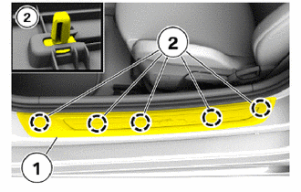
Attach the clips (2) to install the front door scuff plate outside LH (1).
67911B
2.INSTALL FRONT DOOR SCUFF PLATE OUTSIDE RH
- HINT:
-
Use the same procedure as for the LH side.
55317
3.INSTALL INSTRUMENT PANEL PATCH
- HINT:
- ·
Perform this procedure only when replacement of the instrument panel patch is necessary.
·Use the same procedures for the opposite side.
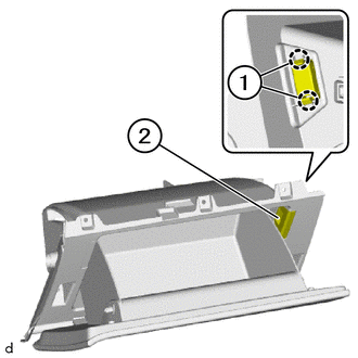
Attach the claws (1) to install the instrument panel patch (2).
4.INSTALL GLOVE BOX LIGHT (w/ Glove Box Light)
- HINT:
-
Perform this procedure only when replacement of the glove compartment door assembly is necessary.
-
Click hereVehicle Interior>LIGHTING (INT)>GLOVE BOX LIGHT>INSTALLATION
55962
5.INSTALL NO. 2 SIDE DEFROSTER NOZZLE
- HINT:
-
Perform this procedure only when replacement of the No. 2 side defroster nozzle is necessary.
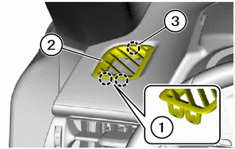
Attach the guide (3) and claws (1) to install the No. 2 side defroster nozzle (2).
55961
6.INSTALL NO. 1 SIDE DEFROSTER NOZZLE
- HINT:
-
Use the same procedure as for the No. 2 side.
84330
7.INSTALL HAZARD WARNING SIGNAL SWITCH ASSEMBLY
- HINT:
-
Perform this procedure only when replacement of the No. 2 instrument panel register assembly is necessary.
-
Click hereVehicle Exterior>LIGHTING (EXT)>HAZARD WARNING SWITCH>INSTALLATION
55054
8.INSTALL GLOVE COMPARTMENT DOOR STOPPER SUB-ASSEMBLY
- HINT:
-
Perform this procedure only when replacement of the glove compartment door stopper sub-assembly is necessary.
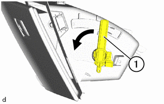

|
Turn in this Direction |
Open the glove compartment door assembly slightly.
Turn the glove compartment door stopper sub-assembly (1) counterclockwise approximately 90° and install it.
Install the locking pin.
84110
9.INSTALL NO. 1 LIGHT CONTROL SWITCH ASSEMBLY
- HINT:
-
Perform this procedure only when replacement of the instrument panel finish panel sub-assembly is necessary.
-
Click hereVehicle Interior>INTERIOR PANELS / TRIM>COMBINATION SWITCH (for Instrument Panel)>INSTALLATION
89611
10.INSTALL PUSH START SWITCH
- HINT:
-
Perform this procedure only when replacement of the No. 1 instrument panel garnish sub-assembly is necessary.
- ·
for B48:
Click hereEngine / Hybrid System>B48 (STARTING)>ENGINE SWITCH>INSTALLATION
·for B58:
Click hereEngine / Hybrid System>B58 (STARTING)>ENGINE SWITCH>INSTALLATION
86120A
11.INSTALL RADIO RECEIVER SWITCH KNOB
- HINT:
-
Perform this procedure only when replacement of the No. 1 instrument panel garnish sub-assembly is necessary.
-
Click hereAudio / Visual / Telematics>AUDIO / VIDEO>CONTROL PANEL>INSTALLATION
69065A
12.INSTALL AIRBAG CUT OFF SWITCH CYLINDER SUB-ASSEMBLY (w/ Airbag Cut Off Switch)
- HINT:
-
Perform this procedure only when replacement of the instrument side panel is necessary.
-
Click hereVehicle Interior>SUPPLEMENTAL RESTRAINT SYSTEMS>AIRBAG CUT-OFF SWITCH>INSTALLATION
13.INSTALL INSTRUMENT PANEL SAFETY PAD ASSEMBLY
Attach the guides (2) to install the instrument panel safety pad assembly (1).
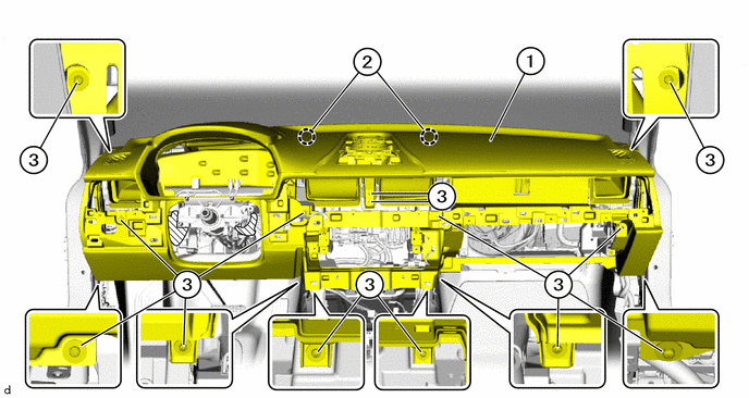

|
Protective Tape | - | - |
Remove the protective Tape.
Tighten the T20 screws (3).
- Torque:
- 1.8 N*m (18 kgf*cm, 16 in.*lbf)
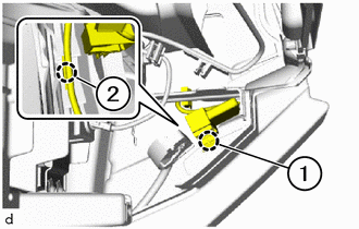
Attach the clips (1) and clips (2) of wiring harness.
Instrument panel passenger airbag assembly for Single Type:
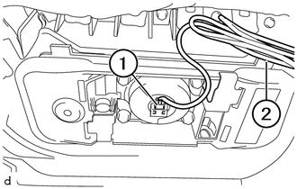
Connect and lock the connector (1) and attach the clip (2).
Instrument panel passenger airbag assembly for Dual Type:
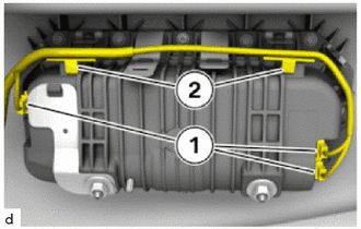
Connect and lock the connectors (1) and attach the clips (2).
55414A
14.INSTALL INSTRUMENT CLUSTER FINISH END PANEL (w/ Headup Display)
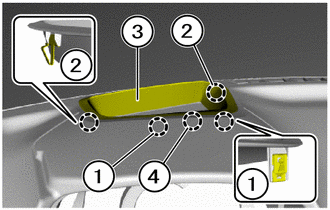
Attach the clips (2), clips (1) and guide (4) to install the instrument cluster finish end panel (3).
45286
15.INSTALL STEERING COLUMN COVER
Install the steering column cover.
86110B
16.INSTALL MULTI-DISPLAY ASSEMBLY
86160J
17.INSTALL FRONT NO. 3 SPEAKER ASSEMBLY (w/ Front Center Speaker)
86160L
18.INSTALL FRONT NO. 4 SPEAKER ASSEMBLY (w/ Front Center Speaker)
55422C
19.INSTALL INSTRUMENT CLUSTER FINISH CENTER UPPER PANEL
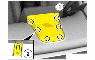
Attach the clips (2) to install the instrument cluster finish center upper panel (1).
62212
20.INSTALL FRONT PILLAR GARNISH LH
Remove the adhesive tape and protective cover.
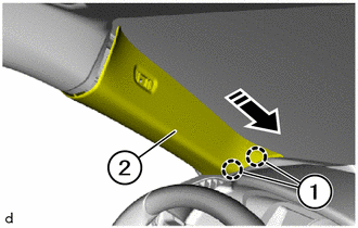

|
Install in this Direction |
Attach the guides (1) of front pillar garnish LH (2) in the direction of the arrow.
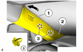
|
|
Install in this Direction |
Attach the clips (3) to install the front pillar garnish LH (2).
Tighten the T25 screw.
- Torque:
- 2.5 N*m (25 kgf*cm, 22 in.*lbf)
Install the front pillar garnish cover LH (1).
62211
21.INSTALL FRONT PILLAR GARNISH RH
- HINT:
-
Use the same procedure as for the LH side.
55660
22.INSTALL NO. 2 INSTRUMENT PANEL REGISTER ASSEMBLY
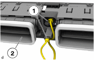
Connect connectors (1) and lock to No. 2 instrument panel register assembly (2).
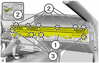
Attach the guides (3) and clips (2) to install the No. 2 instrument panel register assembly (1).
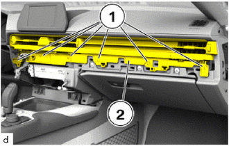
Tighten the T20 screws (1) on the No. 2 instrument panel register assembly (2).
- Torque:
- 2.3 N*m (23 kgf*cm, 20 in.*lbf)
55650
23.INSTALL NO. 1 INSTRUMENT PANEL REGISTER ASSEMBLY
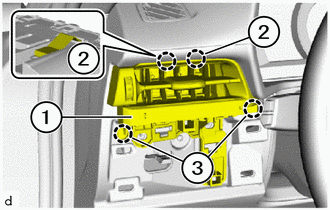
Attach the guides (3) and clips (2) to install the No. 1 instrument panel register assembly (1).
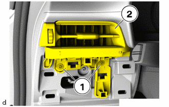
Tighten the T20 screws (1) on the No. 1 instrument panel register assembly (2).
- Torque:
- 2.3 N*m (23 kgf*cm, 20 in.*lbf)
55550
24.INSTALL GLOVE COMPARTMENT DOOR ASSEMBLY
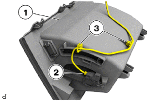
Attach the clips (3) of the wiring harness to the glove compartment door assembly (1).
Connect connector (2) and lock.
w/ Glove Box Light:
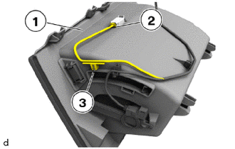
Attach the clip (3) of the wiring harness to the glove compartment door assembly (1).
Connect connector (2) and lock.
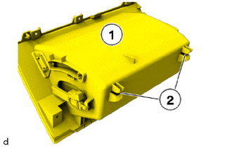
Make sure that the holders (2) on the glove compartment door assembly (1) are positioned correctly during installation.
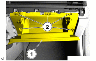
Install the glove compartment door assembly (1).
Open the glove compartment door assembly (1).
Tighten the T20 screws (2).
- Torque:
- 1.8 N*m (18 kgf*cm, 16 in.*lbf)
25.INSTALL GLOVE COMPARTMENT DOOR LOCK CYLINDER ASSEMBLY
- HINT:
-
Perform this procedure only when replacement of the glove compartment door lock cylinder assembly is necessary.
When replacing the glove compartment door lock cylinder assembly with a new one:
Line up the new tumblers in order starting with the smallest numbered tumbler as shown in the illustration.
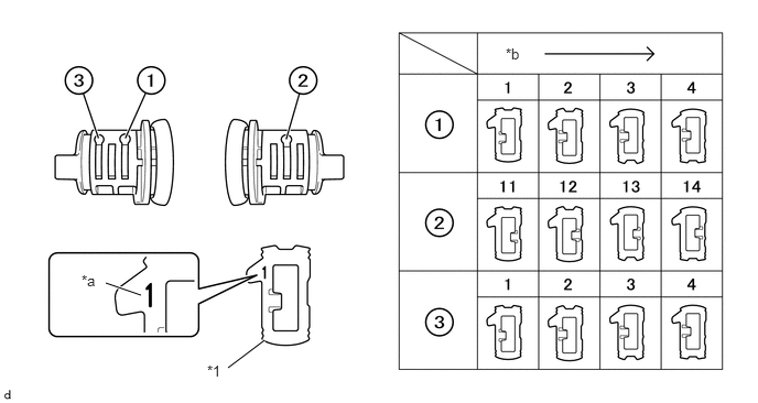
| *1 | Tumbler | - | - |
| *a | Number | *b | Installation Sequence |
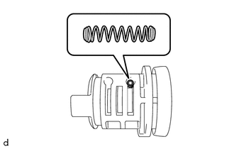
Insert a new spring into the glove compartment door lock cylinder assembly. (Step A)
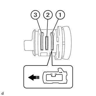
|
|
Install in this Direction |
Insert the smallest numbered tumbler into location (1) of the glove compartment door lock cylinder assembly until it locks in place. (Step B)
Perform Step A and Step B for locations (2) and (3) as well.
Insert the vehicle key into the glove compartment door lock cylinder assembly. (Step C)
Check that the installed tumbler is flush with the glove compartment door lock cylinder assembly. (Step D)
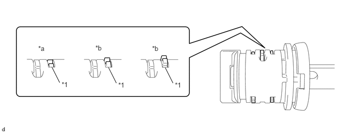
| *1 | Tumbler | - | - |
| *a | Correct | *b | Incorrect |
If the tumbler is not flush with the glove compartment door lock cylinder assembly:
Replace the tumbler that is not flush with the next larger numbered tumbler.
- HINT:
-
Repeat Step B through Step D until all tumblers are flush with the glove compartment door lock cylinder assembly.
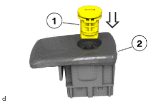

|
Install in this Direction |
Replace opener (2).
Insert glove compartment door lock cylinder assembly (1) in the opener (2) and push in direction of arrow to the limit position.
- NOTICE:
-
The glove compartment door lock cylinder assembly (1) must audibly engage.
Insert the vehicle key into the glove compartment door lock cylinder assembly and check that it rotates smoothly.
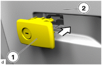
|
|
Install in this Direction |
Position opener (1) in the glove compartment door assembly (2) and push in direction of arrow until the opener (1) engages completely.
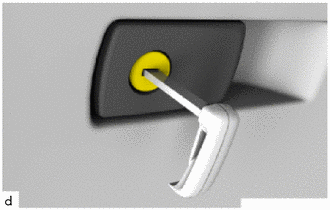
Check glove compartment door lock cylinder assembly for function.
55011A
26.INSTALL NO. 1 INSTRUMENT PANEL GARNISH SUB-ASSEMBLY
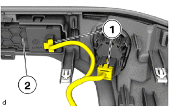
Connect connectors (1) and lock to No. 1 instrument panel garnish sub-assembly (2).
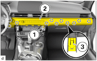
Attach the clips (3) to install the No. 1 instrument panel garnish sub-assembly (2).
Tighten the T20 screw (1).
- Torque:
- 1.8 N*m (18 kgf*cm, 16 in.*lbf)
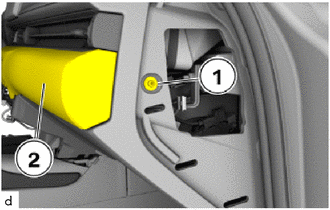
Tighten the T20 screw (1) on the No. 1 instrument panel garnish sub-assembly (2).
- Torque:
- 1.8 N*m (18 kgf*cm, 16 in.*lbf)
55403F
27.INSTALL INSTRUMENT PANEL FINISH PANEL SUB-ASSEMBLY
Connect and lock the connector to the instrument panel finish panel sub-assembly.
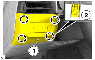
Attach the clips (2) to install the instrument panel finish panel sub-assembly (1).
28.INSTALL COMBINATION METER ASSEMBLY
55318F
29.INSTALL NO. 2 INSTRUMENT SIDE PANEL
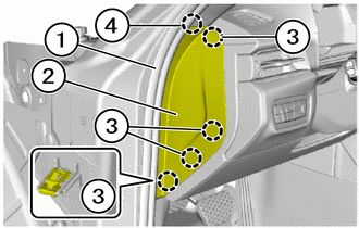
Attach the guide (4) and clips (3) to install the No. 2 instrument side panel (2).
Connect the front door opening trim weatherstrip LH (1) to the area of the No. 2 instrument side panel (2).
55317E
30.INSTALL NO. 1 INSTRUMENT SIDE PANEL
- HINT:
-
Use the same procedure as for the No. 2 side.
w/ Airbag Cut Off Switch:
Connect connector and lock.
Attach the guide and clips to install the No. 1 instrument side panel.
Connect the front door opening trim weatherstrip RH to the area of the No. 1 instrument side panel.
62111C
31.INSTALL COWL SIDE TRIM BOARD RH
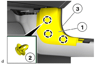
Attach the clips (2) to install the cowl side trim board RH (1).
Make sure the cowl side trim board RH (1) is correctly fitted on the edge protection (3).
62112A
32.INSTALL COWL SIDE TRIM SUB-ASSEMBLY LH
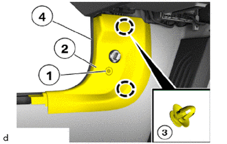
Attach the clips (3) to install the cowl side trim sub-assembly LH (2).
Make sure the cowl side trim sub-assembly LH (2) is correctly fitted on the edge protection (4).
Tighten the T20 screw (1).
- Torque:
- 2.0 N*m (20 kgf*cm, 18 in.*lbf)
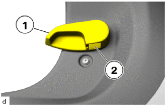
Install the hood lock release lever protector (1).
Install the locking wedge (2).
67914
33.INSTALL FRONT DOOR SCUFF PLATE LH
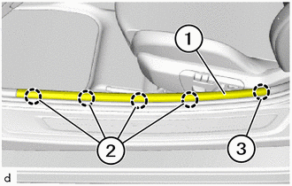
Attach the clips (2) and guide (3) to install the front door scuff plate LH (1).
67913
34.INSTALL FRONT DOOR SCUFF PLATE RH
- HINT:
-
Use the same procedure as for the LH side.
84310
35.INSTALL TURN SIGNAL SWITCH ASSEMBLY
58801D
36.INSTALL CONSOLE BOX ASSEMBLY