B48 ENGINE MECHANICAL BALANCESHAFT INSTALLATION
PROCEDURE

 13621
1.INSTALL NO. 1 BALANCE SHAFT
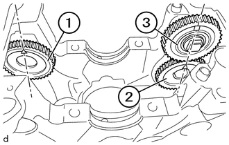
Mount the gears (1), (2) and (3) so that the marks point up to the oil pan sub-assembly sealing surface.
- Distinguishing marks on the gears:
Symbol Gear Triangle Gear (1) on intake side 2 squares Gear (2) on exhaust side Square Gear (3) on exhaust side
- HINT:
-
The gears are distinguished by means of symbols and letters.
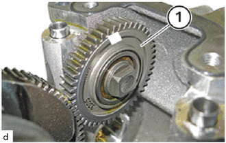
Replace the No. 2 balance shaft driven gear (1).
Install the No. 2 balance shaft driven gear (1).
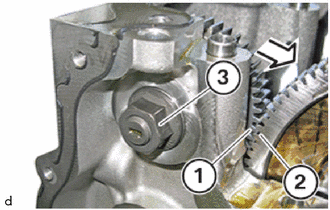
Bring No. 2 balance shaft driven gear (1) in the direction of the arrow into contact with gear (2).
Tighten nut (3).
- Torque:
- 70 N*m (714 kgf*cm, 52 ft.*lbf)
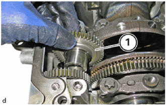
Observe the marking on the No. 1 balance shaft driven gears (1).
- Distinguishing marks on the gears:
Letter Gear A Gear on exhaust side E Gear on intake side
- HINT:
-
The gears are distinguished by means of symbols and letters.
Replace the No. 1 balance shaft driven gear (1).
Install the No. 1 balance shaft driven gear (1).
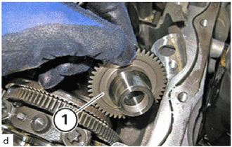
Observe the marking on the No. 1 balance shaft driven gears (1).
- Distinguishing marks on the gears:
Letter Gear A Gear on exhaust side E Gear on intake side
- HINT:
-
The gears are distinguished by means of symbols and letters.
Replace the No. 1 balance shaft driven gear (1).
Install the No. 1 balance shaft driven gear (1).
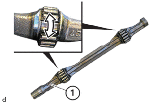
Check all needle bearings of the No. 1 balance shafts (1) for damage and replace as necessary.
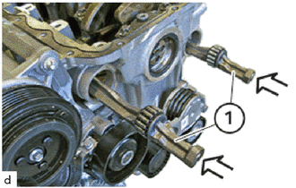
Carefully install the No. 1 balance shaft (1) in the crankcase in the direction of the arrow.
- NOTICE:
- ·
Damage to the crankcase.
If the No. 1 balance shafts are removed or installed incorrectly, they could fall in the bearing positions.
-Remove and install the No. 1 balance shafts slowly and carefully.
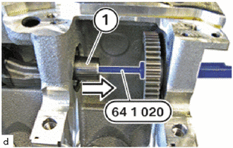
Push special tool 0 493 681 (64 1 020) through the No. 1 balance shaft driven gear into the No. 1 balance shaft.
- SST
- 09200-WA280
Carefully insert the NO. 1 balance shaft (1) into the No. 1 balance shaft driven gear on the intake side.
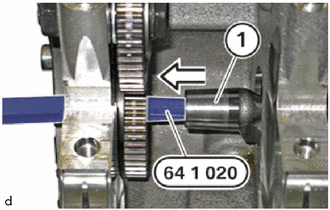
Push special tool 0 493 681 (64 1 020) through the No. 1 balance shaft driven gear into the No. 1 balance shaft.
Carefully insert the No. 1 balance shaft (1) into the No. 1 balance shaft driven gear on the exhaust side.
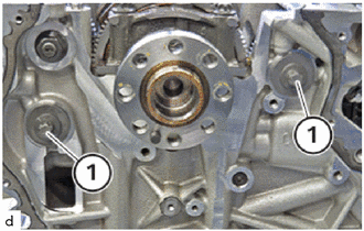
Screw E14 bolts (1) on the left and right a few turns into the No. 1 balance shafts.
Do not tighten E14 bolts (1) so that the No. 1 balance shafts can still be positioned in the next step.
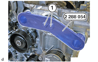
Rotate the crankshaft to the TDC of cylinder 1.
Install special tool 2 288 054 and apply the bolts (1) hand-tight.
- SST
- 09200-WA850
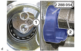
Make sure the special tool 2 288 054 is correctly fitted in the guides (1) of the No. 1 balanceshaft (2).
- SST
- 09200-WA850
- HINT:
-
The description is for one component only. The procedure is identical for all further components.
If necessary, turn the crankshaft slightly.
Tighten special tool 2 288 054.
- SST
- 09200-WA850
- Torque:
- 20 N*m (204 kgf*cm, 15 ft.*lbf)
Tighten the E14 bolts (1).
- Torque:
- 40 N*m (408 kgf*cm, 30 ft.*lbf)
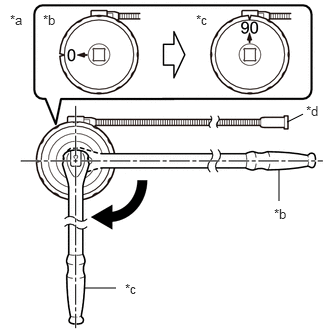
Using SST, tighten the E14 bolt (1) an additional 70°.
- SST
- 09900-WA010
- HINT:
-
 2.99,1.271 3.156,1.188 false 2.906,2.094 2.906,1.76 false 0.875,3 1.208,3 false 0.104,0.125 0.417,0.281 0.313,0.156 10 false *a 0.448,0.125 0.76,0.281 0.313,0.156 10 false *b 2.042,0.125 2.354,0.281 0.313,0.156 10 false *c 3.188,1.073 3.427,1.271 0.24,0.198 10 false *d 2.854,2.146 3.167,2.302 0.313,0.156 10 false *b 1.302,2.927 1.615,3.083 0.313,0.156 10 false *c
*a Example *b Before Tightening *c After Tightening *d Magnetic Portion
- ·
The magnetic portion is used to secure the gauge to the vehicle.
·After first adjusting the needle of the gauge to 0°, tighten to the specified angle.
·Perform the work procedure carefully so that the gauge, etc. does not become tilted.
Loosen bolts (1).
Guide the special tool 2 288 054 out and remove.
- SST
- 09200-WA850
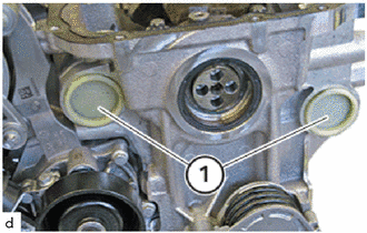
Replace the sealing cap (1).
Make sure the O-rings of the sealing cap (1) are fitted correctly.
Mount both sealing caps.
12121
2.INSTALL NO. 1 OIL PAN BAFFLE PLATE
15100
3.INSTALL OIL PUMP ASSEMBLY
11321
4.INSTALL TIMING GEAR CASE