B48 ENGINE MECHANICAL CRANKSHAFT REASSEMBLY
PROCEDURE

 11711
1.INSTALL CRANKSHAFT BEARING
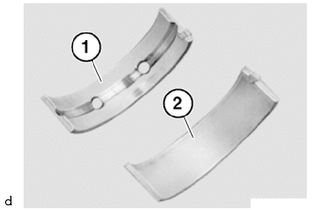
Replace crankshaft bearings with lubricating groove(1) and the crankshaft bearings (2).
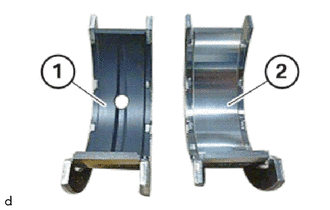
Replace upper crankshaft thrust washer with lubricating groove (1) and lower crankshaft thrust washer (2).
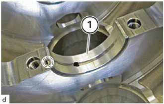
Make sure the crankshaft bearing (1) is correctly installed with the claw in the highlighted area.
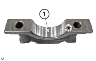
Make sure the crankshaft bearing (1) is correctly installed with the claw in the highlighted area.
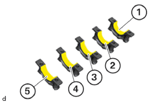
Install crankshaft bearings (1) to (2) and (4) to (5) into the crankshaft bearing cap.
Install the lower crankshaft thrust washer (3) in the crankshaft bearing cap.
Oil all crankshaft bearings and lower crankshaft thrust washers (1) to (5).
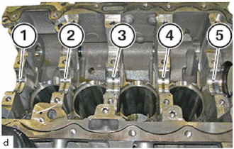
Install crankshaft bearings with lubricating groove (1) to (2) and(4) to (5) in the crankcase.
Install the upper crankshaft thrust washer with lubricating groove (3) in the crankcase.
Oil all crankshaft bearings and upper crankshaft thrust washer with lubricating groove (1) to (5).
13411
2.INSTALL CRANKSHAFT
- NOTICE:
- ·
Engine damage may result from incorrectly installing crankshaft bearings and crankshaft bearing caps.
-Always install all crankshaft bearings and crankshaft bearing caps in the same position from which they were removed.
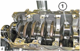
Install the crankshaft (1).
- CAUTION:
- ·
Heavy component.
Heavy components can lead to injury or damage.
-Remove and install heavy components with the aid of another person/other persons.
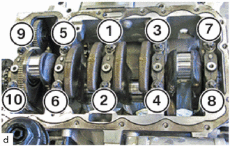
Observe the assignment and the numbering of the crankshaft bearing caps.
- HINT:
- ·
The crankshaft bearing cap, main bearing shell and guide bearing shell are aligned with each other.
Always install the crankshaft bearing cap, main bearing shells and guide bearing shells in the cylinder from which they were removed.
Position the crankshaft bearing cap.
Replace bolts (1) to (10).
Step 1:
Tighten the E14 bolts in sequence (1) to (10).
- Torque:
- 25 N*m (255 kgf*cm, 18 ft.*lbf)
Step 2:
Tighten the bolts 65° in the order shown in step 1 with the special tool 0 490 504 (00 9 120).
- SST
- 09900-WA010
- HINT:
-
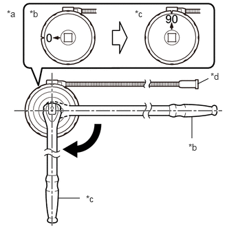 2.99,1.271 3.156,1.188 false 2.906,2.094 2.906,1.76 false 0.875,3 1.208,3 false 0.104,0.125 0.417,0.281 0.313,0.156 10 false *a 0.448,0.125 0.76,0.281 0.313,0.156 10 false *b 2.042,0.125 2.354,0.281 0.313,0.156 10 false *c 3.188,1.073 3.427,1.271 0.24,0.198 10 false *d 2.854,2.146 3.167,2.302 0.313,0.156 10 false *b 1.302,2.927 1.615,3.083 0.313,0.156 10 false *c
*a Example *b Before Tightening *c After Tightening *d Magnetic Portion
- ·
The magnetic portion is used to secure the gauge to the vehicle.
·After first adjusting the needle of the gauge to 0°, tighten to the specified angle.
·Perform the work procedure carefully so that the gauge, etc. does not become tilted.
Step 3:
Tighten the bolts another 65° in the order shown in step 1 with the special tool 0 490 504 (00 9 120).
- SST
- 09900-WA010
- HINT:
-
2.99,1.271 3.156,1.188 false 2.906,2.094 2.906,1.76 false 0.875,3 1.208,3 false 0.104,0.125 0.417,0.281 0.313,0.156 10 false *a 0.448,0.125 0.76,0.281 0.313,0.156 10 false *b 2.042,0.125 2.354,0.281 0.313,0.156 10 false *c 3.188,1.073 3.427,1.271 0.24,0.198 10 false *d 2.854,2.146 3.167,2.302 0.313,0.156 10 false *b 1.302,2.927 1.615,3.083 0.313,0.156 10 false *c
*a Example *b Before Tightening *c After Tightening *d Magnetic Portion
- ·
The magnetic portion is used to secure the gauge to the vehicle.
·After first adjusting the needle of the gauge to 0°, tighten to the specified angle.
·Perform the work procedure carefully so that the gauge, etc. does not become tilted.
Step 4:
Release E14 bolts (1) to (10).
Step 5:
Tighten the E14 bolts in sequence (1) to (10).
- Torque:
- 25 N*m (255 kgf*cm, 18 ft.*lbf)
Step 6:
Tighten the bolts 65° in the order shown in step 1 with the special tool 0 490 504 (00 9 120).
- SST
- 09900-WA010
- HINT:
-
2.99,1.271 3.156,1.188 false 2.906,2.094 2.906,1.76 false 0.875,3 1.208,3 false 0.104,0.125 0.417,0.281 0.313,0.156 10 false *a 0.448,0.125 0.76,0.281 0.313,0.156 10 false *b 2.042,0.125 2.354,0.281 0.313,0.156 10 false *c 3.188,1.073 3.427,1.271 0.24,0.198 10 false *d 2.854,2.146 3.167,2.302 0.313,0.156 10 false *b 1.302,2.927 1.615,3.083 0.313,0.156 10 false *c
*a Example *b Before Tightening *c After Tightening *d Magnetic Portion
- ·
The magnetic portion is used to secure the gauge to the vehicle.
·After first adjusting the needle of the gauge to 0°, tighten to the specified angle.
·Perform the work procedure carefully so that the gauge, etc. does not become tilted.
Step 7:
Tighten the bolts another 65° in the order shown in step 1 with the special tool 0 490 504 (00 9 120).
- SST
- 09900-WA010
- HINT:
-
2.99,1.271 3.156,1.188 false 2.906,2.094 2.906,1.76 false 0.875,3 1.208,3 false 0.104,0.125 0.417,0.281 0.313,0.156 10 false *a 0.448,0.125 0.76,0.281 0.313,0.156 10 false *b 2.042,0.125 2.354,0.281 0.313,0.156 10 false *c 3.188,1.073 3.427,1.271 0.24,0.198 10 false *d 2.854,2.146 3.167,2.302 0.313,0.156 10 false *b 1.302,2.927 1.615,3.083 0.313,0.156 10 false *c
*a Example *b Before Tightening *c After Tightening *d Magnetic Portion
- ·
The magnetic portion is used to secure the gauge to the vehicle.
·After first adjusting the needle of the gauge to 0°, tighten to the specified angle.
·Perform the work procedure carefully so that the gauge, etc. does not become tilted.
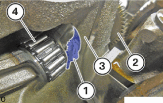
Guide out cloth (1) between No. 1 balanceshaft (2) on the intake side and crankcase (3) and remove it.
Ensure that needle bearing (4) is not damaged.
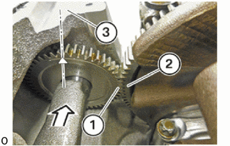
Bring or adjust crankshaft (2) to the TDC position.
Position No. 1 balanceshaft (1) on the intake side in the direction of the arrow on crankshaft (2).
The mark on gear (1) on the intake side of the No. 1 balanceshaft must point upwards, perpendicular to the sealing surface of oil pan sub-assembly (3).
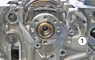
Replace the bolt (1).
Tighten E14 bolt (1) into the No. 1 balanceshaft on the intake side.
Do not tighten E14 bolt (1) since otherwise the No. 1 balanceshaft can no longer be positioned in the next step.
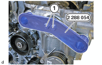
Rotate the crankshaft to the TDC of the first cylinder.
Mount the special tool 2 288 054 and abut the bolts (1).
- SST
- 09200-WA850
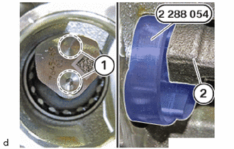
Make sure the special tool 2 288 054 is correctly fitted in the guides (1) of the No. 1 balanceshaft (2).
- SST
- 09200-WA850
If necessary, turn the crankshaft slightly.
Tighten special tool 2 288 054 .
- SST
- 09200-WA850
- Torque:
- 20 N*m (204 kgf*cm, 15 ft.*lbf)
Tighten E14 bolt (1) of the No. 1 balanceshaft on the intake side.
- Torque:
- 40 N*m (408 kgf*cm, 30 ft.*lbf)
Using SST, tighten the E14 bolt No. 1 balanceshaft on the intake side (1) an additional 70°.
- SST
- 09900-WA010
- HINT:
-
2.99,1.271 3.156,1.188 false 2.906,2.094 2.906,1.76 false 0.875,3 1.208,3 false 0.104,0.125 0.417,0.281 0.313,0.156 10 false *a 0.448,0.125 0.76,0.281 0.313,0.156 10 false *b 2.042,0.125 2.354,0.281 0.313,0.156 10 false *c 3.188,1.073 3.427,1.271 0.24,0.198 10 false *d 2.854,2.146 3.167,2.302 0.313,0.156 10 false *b 1.302,2.927 1.615,3.083 0.313,0.156 10 false *c
*a Example *b Before Tightening *c After Tightening *d Magnetic Portion
- ·
The magnetic portion is used to secure the gauge to the vehicle.
·After first adjusting the needle of the gauge to 0°, tighten to the specified angle.
·Perform the work procedure carefully so that the gauge, etc. does not become tilted.
Loosen bolts (1).
Guide the special tool 2 288 054 out and remove.
- SST
- 09200-WA850
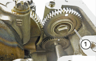
Guide in and install No. 2 balanceshaft driven gear (1).
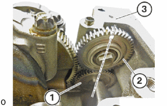
The marks on gear (1) and also on No. 2 balanceshaft driven gear (2) must point upwards, perpendicular to the sealing surface of oil pan sub-assembly (3).
Mark on No. 2 balanceshaft driven gear (2) of the counterbalance shaft on the exhaust side: a square.
Mark on gear (1) of the No. 1 balanceshaft on the exhaust side: a triangle.
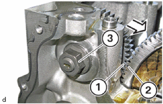
Move No. 2 balanceshaft driven gear (1) in the direction of the arrow to gear (2) of the crankshaft.
Tighten nut (3).
- Torque:
- 70 N*m (714 kgf*cm, 52 ft.*lbf)
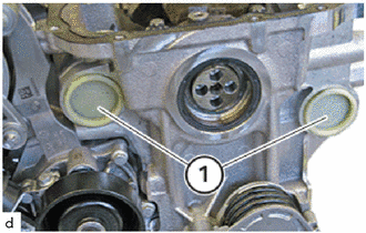
Replace the sealing cap (1).
Make sure the O-rings of the sealing cap (1) are fitted correctly.
Mount both sealing caps (1).
3.INSPECT CRANKSHAFT THRUST CLEARANCE
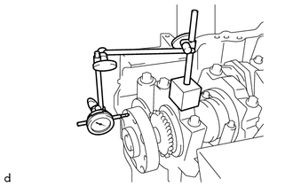
Using a dial indicator, check crankshaft thrust clearance.
- Axial play of crankshaft:
0.1 to 0.254 mm (0.0039 to 0.0100 in.)
- HINT:
-
If the thrust clearance is not as specified, replace worn components.
13411
4.INSPECT CRANKSHAFT
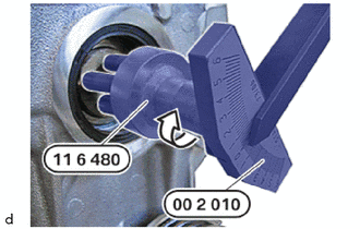
Turn the crankshaft clockwise with the special tool 0 490 130 (00 2 010) and compare the reading on the scale to the maximum permitted torque.
- SST
- 09200-WA360
- Maximum permitted torque of the crankshaft:
8.0 N*m (82 kgf*cm, 71 in.*lbf)
- HINT:
-
If the maximum permitted torque is exceeded, correct the radial clearance.
5.INSPECT PISTON
6.INSPECT CYLINDER BORE
13201
7.INSTALL CONNECTING ROD SUB-ASSEMBLY
12121
8.INSTALL NO. 1 OIL PAN BAFFLE PLATE
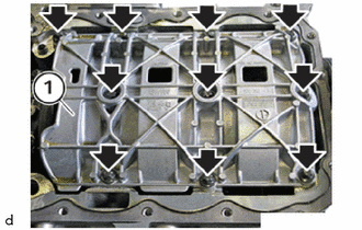
Install the No. 1 oil pan baffle plate.
Replace the bolts.
Tighten the E10 bolts in a crosswise pattern.
- Torque:
- 15 N*m (153 kgf*cm, 11 ft.*lbf)
Using SST, tighten the E10 bolt (1) an additional 45°.
- SST
- 09900-WA010
- HINT:
-
2.99,1.271 3.156,1.188 false 2.906,2.094 2.906,1.76 false 0.875,3 1.208,3 false 0.104,0.125 0.417,0.281 0.313,0.156 10 false *a 0.448,0.125 0.76,0.281 0.313,0.156 10 false *b 2.042,0.125 2.354,0.281 0.313,0.156 10 false *c 3.188,1.073 3.427,1.271 0.24,0.198 10 false *d 2.854,2.146 3.167,2.302 0.313,0.156 10 false *b 1.302,2.927 1.615,3.083 0.313,0.156 10 false *c
*a Example *b Before Tightening *c After Tightening *d Magnetic Portion
- ·
The magnetic portion is used to secure the gauge to the vehicle.
·After first adjusting the needle of the gauge to 0°, tighten to the specified angle.
·Perform the work procedure carefully so that the gauge, etc. does not become tilted.
13507A
9.INSTALL OIL PUMP DRIVE CHAIN SUB-ASSEMBLY
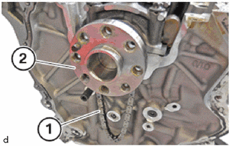
Guide in and install oil pump drive chain sub-assembly (1) on crankshaft (2).
15100
10.INSTALL OIL PUMP ASSEMBLY
13506
11.INSTALL CHAIN SUB-ASSEMBLY
11321
12.INSTALL TIMING GEAR CASE
13.INSTALL TIMING CHAIN COVER OIL SEAL
12101
14.INSTALL OIL PAN SUB-ASSEMBLY
- NOTICE:
- ·
Contaminant or foreign body.
Contamination can result in malfunctions, operating failure or leaks.
-Adhere to the utmost cleanliness.
-Protect components from contamination e.g. by covering.
-Close off line connections with seal plugs.
- ·
Damage to the surface.
The use of metal-cutting tools (e.g. sandpaper) to clean the surfaces can damage them and lead to leaks or engine damage.
-Do not use any metal-cutting tools.
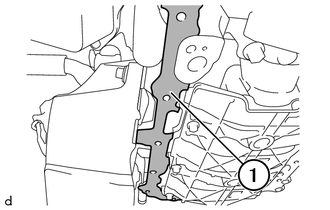
Remove coarse seal packing remains on the sealing surface of the cylinder block (1) and the sealing surface on the oil pan sub-assembly.
- NOTICE:
-
The sealing surfaces must be free from oils, grease and cleaning agents.
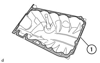
Remove fine seal packing remains on the sealing surface of the oil pan sub-assembly (1) and the sealing surface on the cylinder block.
- NOTICE:
-
The sealing surfaces must be free from oils, grease and cleaning agents.
Load the sealer gun with the seal packing.
- Seal Packing:
Loctite 5970 Flange Sealant
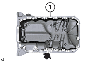
Apply sealing bead (1) with the seal packingin the marked area along the inner edge.
- Height of the sealing bead:
2.0 to 2.5 mm (0.0787 to 0.0984 in.)
- NOTICE:
- ·
The application time of the liquid sealing compound can be at a maximum of 10 min.
·Start-up of the assembly is not possible until 25 minutes after the application time.
·Non-observance can lead to leaks in the assembly.
Completely encircle the oil return orifice (arrow) with the seal packing.
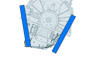
Using a straightedge, position the oil pan sub-assembly and timing case cover so that their surfaces are aligned.
- HINT:
-
The straightedge is only required whenthe transmission is removed.
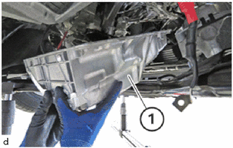
Install oil pan sub-assembly (1) to top front.
Hand-tighten all oil pan sub-assembly bolts but do not tighten completely.
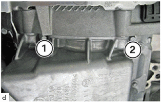
Tighten down E10 bolts (1) and (2).
- Torque:
- 24 N*m (245 kgf*cm, 18 ft.*lbf)
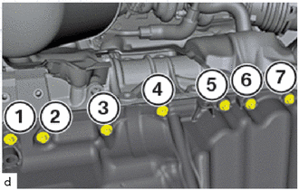
Tighten down E10 bolts (1) to (7).
- Torque:
- 24 N*m (245 kgf*cm, 18 ft.*lbf)
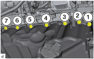
Tighten down E10 bolts (1) to (7).
- Torque:
- 24 N*m (245 kgf*cm, 18 ft.*lbf)
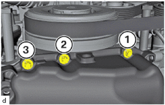
Tighten down E10 bolts (1), (2) and (3).
- Torque:
- 24 N*m (245 kgf*cm, 18 ft.*lbf)
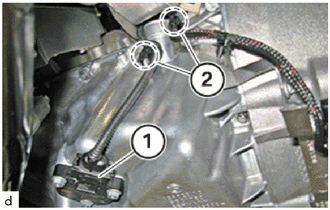
Mount cable with the clips (2) on the oil pan sub-assembly .
Connect connectors (1) and lock.
15.INSTALL DRIVE PLATE AND RING GEAR SUB-ASSEMBLY
16.REMOVE AND INSTALL FRONT CRANKSHAFT OIL SEAL
- HINT:
- ·
When the vibration damper is exchanged, the front crankshaft oil seal must also be renewed.
·The front crankshaft oil seal must be installed dry. Do not use engine oil or lubricant.
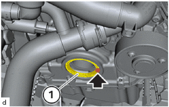
Carefully drive in the front crankshaft oil seal (1) inthe marked area (arrow) using a punch to approx.1 cm deep.
Do not damage the sealing surface on thecylinder block sub-assembly in the process.
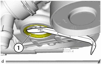
Lever out and remove front crankshaft oil seal (1).
- HINT:
- ·
Scratches.
Tools and sharp-edged componentscan cause scratches.
-Protect working area.
-Handle tools and componentscarefully.
Do not scratch the sealing surface on the cylinder block sub-assembly in the process.
Replace front crankshaft oil seal.
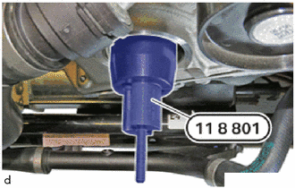
Clean the special tool 0 496 128 (11 8 801) from the set of special tools 0 496 127 (11 8 800) andcoat it with fresh engine oil.
- SST
- 09200-WA080
Secure special tool 0 496 128 (11 8 801) to thecrankshaft using special tool 0 496 129 (11 8 802).
- SST
- 09200-WA080
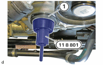
Carefully slide the front crankshaft oil seal (1) in arotational movement onto the special tool 0 496128 (11 8 801) until the front crankshaft oil seal rests against the cylinder block sub-assembly.
- SST
- 09200-WA080
- NOTICE:
- ·
Front crankshaft oil seal damage.
Touching the sealing lip (inner) andapplying oil to the front crankshaft oilseal will lead to its destruction.
-Do not touch the sealing lip (inner)of the front crankshaft oil seal.
-Do not apply oil to the front crankshaft oil seal.
-Install the front crankshaft oil sealdry.
Carefully slide the front crankshaft oil seal (1) in arotational movement onto the special tool 0 496128 (11 8 801) until the front crankshaft oil seal rests against the cylinder block sub-assembly.
- SST
- 09200-WA080
The front crankshaft oil seal must not be tilted in the process.
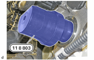
Mount the special tool (sleeve) 0 496 130 (11 8803) on special tool 0 496 128 (11 8 801).
- SST
- 09200-WA080
Screw on the special tool (nut) 0 496 131 (11 8804) until the special tool (sleeve) 0 496 130 (11 8803) lies flush on the cylinder block sub-assembly.
- SST
- 09200-WA080
This correctly positions the front crankshaft oilseal.
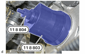
Remove special tools.
13470
17.INSTALL CRANKSHAFT PULLEY ASSEMBLY
18. SEALING OIL DUCT
19. CLEAN SEALING SURFACES
11115
20.INSTALL CYLINDER HEAD GASKET
21.SET NO. 1 CYLINDER TO TDC (COMPRESSION)
- NOTICE:
- ·
Damage to the engine.
The engine may be damaged if it is manually rotated in the wrong direction.
-Always rotate the engine in the correct direction of rotation by hand: a) Clockwise, facing the crankshaft pulley assembly or b) Counter-clockwise, facing the chain sub-assembly. (b) only applies when the chain sub-assembly is installed.
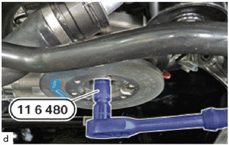
Turn the engine with the special tool 0 493 380 (11 6 480) to the TDC firing position of cylinder 1.
- SST
- 09200-WA190
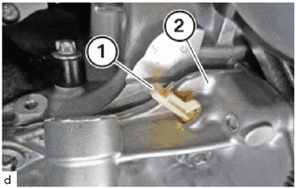
Guide out and remove sealing cap (1) on oil pan sub-assembly (2).
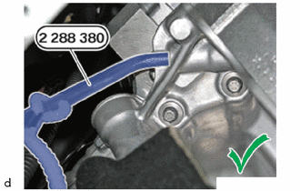
Make sure that the special tool 2 288 380 is positioned correctly .
- SST
- 09200-WA570
The engine is in the TDC firing position of cylinder 1.
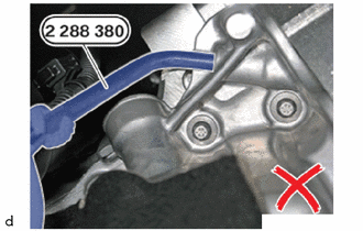
The TDC firing position of the 1st cylinder is not reached and the special tool 2 288 380 is positioned incorrectly: Position the special tool 2 288 380 again.
- SST
- 09200-WA570
11101
22.INSTALL CYLINDER HEAD SUB-ASSEMBLY
16028
23.INSTALL NO. 2 TURBO WATER PIPE SUB-ASSEMBLY
16020
24.INSTALL WATER PUMP ASSEMBLY
25.ADJUST CAMSHAFT
13070A
26.INSTALL CAMSHAFT TIMING EXHAUST GEAR ASSEMBLY
135A0A
27.TEMPORARILY TIGHTEN EXHAUST CAMSHAFT TIMING GEAR BOLT ASSEMBLY
13050
28.INSTALL CAMSHAFT TIMING GEAR ASSEMBLY
135A0
29.TEMPORARILY TIGHTEN INTAKE CAMSHAFT TIMING GEAR BOLT ASSEMBLY
13506
30.TEMPORARILY INSTALL CHAIN SUB-ASSEMBLY
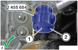
Make sure that the chain sub-assembly is correctly pre-tensioned with the special tool 2 455 654. The pin (1) must be aligned flush with the housing (2).
- SST
- 09200-WA810
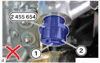
Make sure that the preload of the chain sub-assembly is not insufficient. The preload is insufficient when the pin (1) of the special tool 2 455 654 is not aligned flush with the housing (2). The chain sub-assembly is not correctly preload.
- SST
- 09200-WA810
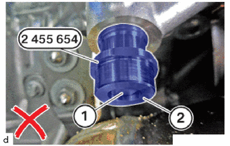
Make sure that the preload of the chain sub-assembly is not too high. The preload is too high when the pin (1) of the special tool 2 455 654 is not aligned flush with the housing (2). The chain sub-assembly is not correctly pre-tensioned.
- SST
- 09200-WA810
135A0A
31.FULLY TIGHTEN EXHAUST CAMSHAFT TIMING GEAR BOLT ASSEMBLY
135A0
32.FULLY TIGHTEN INTAKE CAMSHAFT TIMING GEAR BOLT ASSEMBLY
33.REMOVE SST
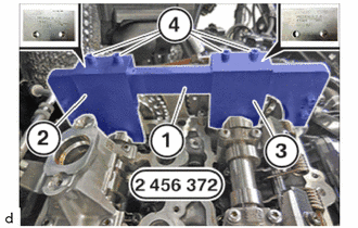
Unscrew the bolts (4) from the set of special tools 2 456 372.
- SST
- 09200-WA700
Feed out the 0.5 ° setting gauge (2) from the set of special tools 2 456 372 between the exhaust camshaft sub-assembly and the basic carrier (1) and remove.
- SST
- 09200-WA700
Feed out the 0.7 ° setting gauge (3) from the set of special tools 2 456 372 between the intake camshaft sub-assembly and the basic carrier (1) and remove.
- SST
- 09200-WA700
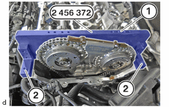
Unscrew the bolts (2) from the set of special tools 2 456 372.
- SST
- 09200-WA700
Feed Thread the basic carrier (1) out of the special tool 2 456 372 and remove.
- SST
- 09200-WA700
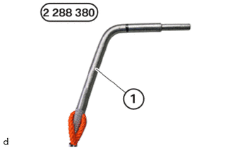
Guide the special tool 2 288 380 out and remove.
- SST
- 09200-WA570
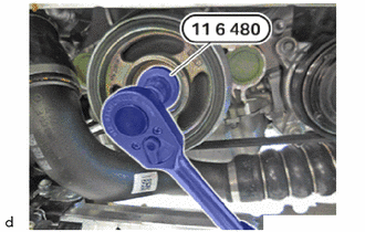
Guide the special tool 0 493 380 (11 6 480) out and remove.
- SST
- 09200-WA190
13540
34.INSTALL NO. 1 CHAIN TENSIONER ASSEMBLY
35.INSPECT CAMSHAFT TIMING
Turn the engine with the special tool 0 493 380 (11 6 480) to the TDC firing position of cylinder 1.
- SST
- 09200-WA190
- NOTICE:
- ·
Damage to the engine.
The engine may be damaged if it is manually rotated in the wrong direction.
-Always rotate the engine in the correct direction of rotation by hand: a) Clockwise, facing the crankshaft pulley assembly or b) Counter-clockwise, facing the timing chain. (b) only applies when the chain sub-assembly is installed.
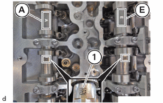
Make sure that the marks (1) on the intake camshaft sub-assembly (E) and the exhaust camshaft sub-assembly (A) are legible from above.
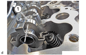
Ensure that the cam (1) on the exhaust camshaft sub-assembly on cylinder 1 points to the inside right at a slight angle.
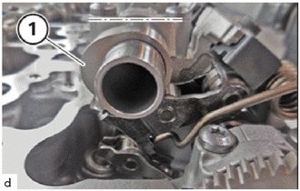
Ensure that the cam (1) on the intake camshaft sub-assembly on cylinder 1 points to the inside left at an angle.
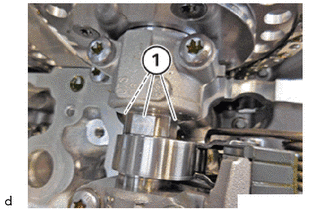
Ensure that the flattened areas (1) on the intake camshaft sub-assembly and the exhaust camshaft sub-assembly point upwards.
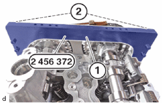
Position the basic carrier (1) from the set of special tools 2 456 372 on the cylinder head sub-assembly.
- SST
- 09200-WA700
Tighten the bolts (2) from the set of special tools 2 456 372.
- SST
- 09200-WA700
- Torque:
- 8.0 N*m (82 kgf*cm, 71 in.*lbf)
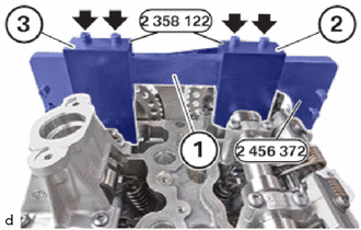
Position the test gauge (2) from the set of special tools 2 358 122 between the intake camshaft sub-assembly and the basic carrier (1) from the set of special tools 2 456 372.
- SST
- 09200-WA380
09200-WA700
Position the test gauge (3) from the set of special tools 2 358 122 between the exhaust camshaft sub-assembly and the basic carrier (1) from the set of special tools 2 456 372.
- SST
- 09200-WA380
09200-WA700
Tighten bolts (arrows).
- Torque:
- 8.0 N*m (82 kgf*cm, 71 in.*lbf)
Guide out and remove sealing cap (1) on oil pan sub-assembly (2).
Position the special tool 2 288 380 correctly in the dowel hole.
- SST
- 09200-WA570
The engine is in the TDC firing position of cylinder 1.
Make sure that the special tool 2 288 380 is not positioned incorrectly.
- SST
- 09200-WA570
The TDC firing position of cylinder 1 was not reached.
36.INSTALL SPARK PLUG
15474
37.INSTALL OUTLET TURBO OIL PIPE
15407
38.INSTALL INLET TURBO OIL PIPE SUB-ASSEMBLY
17111
39.INSTALL INTAKE MANIFOLD
23285A
40.INSTALL NO. 1 CHECK VALVE
11201
41.INSTALL CYLINDER HEAD COVER SUB-ASSEMBLY
15370J
42.INSTALL CAM TIMING OIL CONTROL SOLENOID ASSEMBLY
23250B
43.REPLACE FUEL INJECTOR SEAL
23250
44.INSTALL FUEL INJECTOR ASSEMBLY
23470
45.ADJUST FUEL PUMP LIFTER ASSEMBLY
23100X
46.INSTALL FUEL (ENGINE ROOM SIDE) PUMP ASSEMBLY
23801P
47.INSTALL NO. 1 FUEL PIPE SUB-ASSEMBLY
48.ADD ENGINE OIL
49.INSTALL ENGINE ASSEMBLY