B48 ENGINE MECHANICAL TIMING GEAR CASE INSTALLATION
PROCEDURE

 1.INSTALL CRANK POSITION SENSOR
- NOTICE:
- ·
Electrostatic discharge.
Damage to or destruction of electrical components.
-Only touch the housings of electrical components. Do not touch pins or multi-pinconnectors directly.
-For additional information see:
Click hereGeneral>INTRODUCTION>REPAIR INSTRUCTION>PRECAUTION
Guide in and install crankshaft sensor and install.
Using a 4 mm hexagon socket wrench, tighten down bolt.
- Torque:
- 4.6 N*m (47 kgf*cm, 41 in.*lbf)
Connect connectors and lock.
- HINT:
-
The connector must engage audibly.
11321
2.INSTALL TIMING GEAR CASE
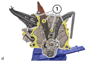
Clean sealing surfaces (1).
- NOTICE:
- ·
Damage to the surface.
The use of metal-cutting tools (e.g. sandpaper) to clean the surfaces can damage them and lead to leaks or engine damage.
-Do not use any metal-cutting tools.
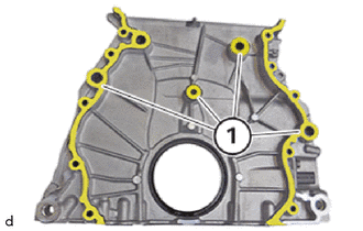
Clean sealing surfaces (1).
- NOTICE:
- ·
Damage to the surface.
The use of metal-cutting tools (e.g. sandpaper) to clean the surfaces can damage them and lead to leaks or engine damage.
-Do not use any metal-cutting tools.
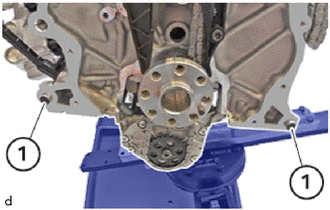
Check the ring pins (1) for damage andreplace if necessary.
Check for correct fit of ring pins(1).
Load the sealer gun with the seal packing.
- Seal Packing:
Loctite 5970 Flange Sealant
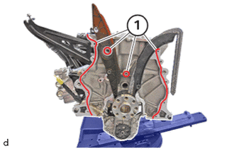
Apply the seal packing in area (1)along the inner edge.
- Height of the sealing bead:
2.0 to 2.5 mm (0.0787 to 0.0984 in.)
- NOTICE:
- ·
The application time of the liquid sealing compound can be at a maximum of 10 min.
·Start-up of the assembly is not possible until 25 minutes after the application time.
·Non-observance can lead to leaks in the assembly.
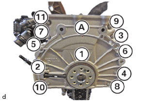
Replace bolts (1) to (11).
Carefully mount the timing case cover (A).
Tighten the E8 bolts in sequence (1) to (11).
- Torque:
- 8.0 N*m (82 kgf*cm, 71 in.*lbf)
Using SST, tighten the E8 bolts an additional 90°.
- SST
- 09900-WA010
- HINT:
-
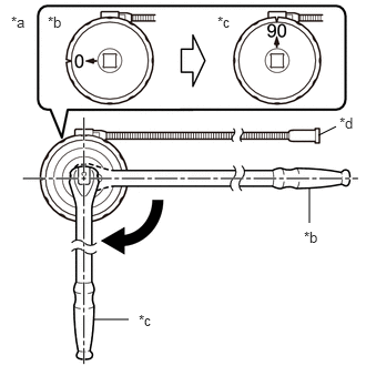 2.99,1.271 3.156,1.188 false 2.906,2.094 2.906,1.76 false 0.875,3 1.208,3 false 0.104,0.125 0.417,0.281 0.313,0.156 10 false *a 0.448,0.125 0.76,0.281 0.313,0.156 10 false *b 2.042,0.125 2.354,0.281 0.313,0.156 10 false *c 3.188,1.073 3.427,1.271 0.24,0.198 10 false *d 2.854,2.146 3.167,2.302 0.313,0.156 10 false *b 1.302,2.927 1.615,3.083 0.313,0.156 10 false *c
*a Example *b Before Tightening *c After Tightening *d Magnetic Portion
- ·
The magnetic portion is used to secure the gauge to the vehicle.
·After first adjusting the needle of the gauge to 0°, tighten to the specified angle.
·Perform the work procedure carefully so that the gauge, etc. does not become tilted.
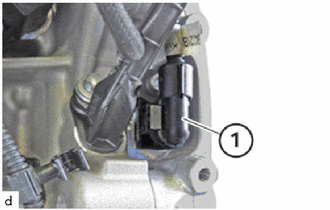
Connect connectors (1) and lock.
The connector (1) must engage audibly.
3.INSTALL TIMING CHAIN COVER OIL SEAL
15100
4.INSTALL OIL PUMP ASSEMBLY
5.INSTALL DRIVE PLATE AND RING GEAR SUB-ASSEMBLY
6.CLEAN SEALING SURFACES
11115
7.INSTALL CYLINDER HEAD GASKET
8.SET NO. 1 CYLINDER TO TDC (COMPRESSION)
11101
9.INSTALL CYLINDER HEAD SUB-ASSEMBLY
10.ADJUST CAMSHAFT
13070A
11.INSTALL CAMSHAFT TIMING EXHAUST GEAR ASSEMBLY
135A0A
12.TEMPORARILY TIGHTEN EXHAUST CAMSHAFT TIMING GEAR BOLT ASSEMBLY
13050
13.INSTALL CAMSHAFT TIMING GEAR ASSEMBLY
135A0
14.TEMPORARILY TIGHTEN INTAKE CAMSHAFT TIMING GEAR BOLT ASSEMBLY
13506
15.TEMPORARILY INSTALL CHAIN SUB-ASSEMBLY
135A0A
16.FULLY TIGHTEN EXHAUST CAMSHAFT TIMING GEAR BOLT ASSEMBLY
135A0
17.FULLY TIGHTEN INTAKE CAMSHAFT TIMING GEAR BOLT ASSEMBLY
18.REMOVE SST
13540
19.INSTALL NO. 1 CHAIN TENSIONER ASSEMBLY
20.INSPECT CAMSHAFT TIMING
21.INSTALL SPARK PLUG
15474
22.INSTALL TURBO OIL OUTLET PIPE
17111
23.INSTALL INTAKE MANIFOLD
23285A
24.INSTALL NO. 1 CHECK VALVE
11201
25.INSTALL CYLINDER HEAD COVER SUB-ASSEMBLY
15370J
26.INSTALL CAM TIMING OIL CONTROL SOLENOID ASSEMBLY
23250B
27.REPLACE FUEL INJECTOR SEAL
23250
28.INSTALL FUEL INJECTOR ASSEMBLY
23470
29.ADJUST FUEL PUMP LIFTER ASSEMBLY
23100X
30.INSTALL FUEL (ENGINE ROOM SIDE) PUMP ASSEMBLY
23801P
31.INSTALL NO. 1 FUEL PIPE SUB-ASSEMBLY
32.ADD ENGINE OIL
33.INSTALL ENGINE ASSEMBLY