B48 ENGINE MECHANICAL ENGINE WIRE HARNESS(for No. 2) INSTALLATION
PROCEDURE

 82122
1.INSTALL NO. 2 ENGINE WIRE
Overview: No. 2 engine wire
- NOTICE:
- ·
Improper routing of cables and wiring harnesses.
Trapped, crushed or damaged cables may cause short circuits and malfunctions.
-Route all cables without abrasions, do not trap and crush.
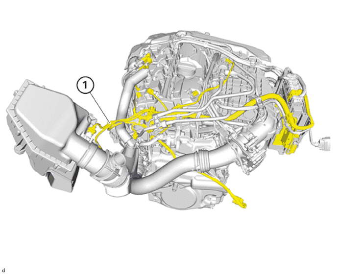
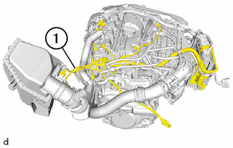
Thread in and install the No. 2 engine wire (1).
Secure all clamps.
Connect and lock the connector of the oil temperature sensor at the cylinder head.
Connect and lock the connector of the intake mass air flow meter sub-assembly.
Connect and lock the connector of the camshaft position sensor (for Intake Side).
Connect and lock the connector of the camshaft position sensor (for Exhaust Side).
Connect and lock the connector of the fuel delivery pipe.
Connect and lock the connector of the fuel pump assembly (for High Pressure).
Connect and lock the connector of the ventilation hose.
Connect and lock the connector of the water pump assembly (for Heater).
The connectors must engage audibly.
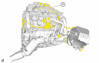
Connect and lock the connector of the wide range air fuel ratio sensor.
Connect the connector of the oxygen sensor and lock.
Connect and lock the connector for the turbocharger actuator and link assembly.
Connect and lock the connector from both cam timing oil control solenoid assemblies.
Connect and lock the connector for the No. 1 check valve.
The connectors must engage audibly.
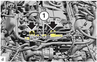
Thread in cable channel (1) and install.
The locks (arrows) must engage audibly.
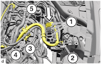
Connect and lock all connectors (1) in the direction of the arrow.
Position engine wiring harness.
Lock holder (2).
Lock holder (3).
Lock holder (4).
Lock holder (5).
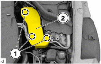
Install the cover (2).
The snap-lock couplings (1) must engage audibly.
11271A
2.INSTALL REAR CYLINDER BLOCK COVER
3.INSTALL NO. 2 CYLINDER BLOCK SIDE COVER
55788A
4.INSTALL COWL TOP VENTILATOR LOUVER PROTECTOR
85010
5.INSTALL FRONT WIPER MOTOR AND LINK ASSEMBLY
12601B
6.INSTALL NO. 1 ENGINE COVER SUB-ASSEMBLY
17880
7.INSTALL AIR CLEANER HOSE ASSEMBLY
17700
8.INSTALL AIR CLEANER ASSEMBLY
9.CONNECT CABLE TO NEGATIVE BATTERY TERMINAL