B48 ENGINE CONTROL CAMSHAFT TIMING GEAR BOLT INSTALLATION
PROCEDURE

 135A0A
1.TEMPORARILY TIGHTEN EXHAUST CAMSHAFT TIMING GEAR BOLT ASSEMBLY
Guide in the exhaust camshaft timing gear bolt assembly and install.
Hand-tighten the exhaust camshaft timing gear bolt assembly.
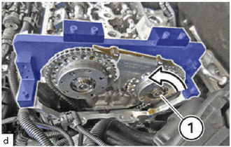
Release the exhaust camshaft timing gear bolt assembly (1) in the direction of arrow by 60°.
135A0
2.TEMPORARILY TIGHTEN INTAKE CAMSHAFT TIMING GEAR BOLT ASSEMBLY
Guide in the intake camshaft timing gear bolt assembly and install.
Hand-tighten the intake camshaft timing gear bolt assembly.
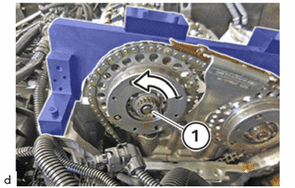
Release the intake camshaft timing gear bolt assembly (1) in the direction of arrow by 60°.
3.REMOVE SST
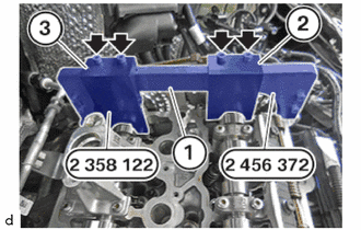
Remove screws (arrows).
Guide the test gauge (2) out of the set of special tools 2 358 122 between the intake camshaft sub-assembly and the basic carrier (1) of the set of special tools 2 456 372 and remove.
- SST
- 09200-WA380
09200-WA700
Guide the test gauge (3) out of the set of special tools 2 358 122 between the exhaust camshaft sub-assembly and the basic carrier (1) of the set of special tools 2 456 372 and remove.
- SST
- 09200-WA380
09200-WA700
4.ADJUST CAMSHAFT
13506
5.TEMPORARILY INSTALL CHAIN SUB-ASSEMBLY
135A0
6.FULLY TIGHTEN INTAKE CAMSHAFT TIMING GEAR BOLT ASSEMBLY
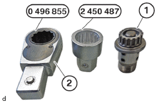
To tighten the intake camshaft timing gear bolt assembly (1) use the special tool 2 450 487, 0 496 855 and SST.
- SST
- 09200-WA470
09200-WA800
09900-WA280
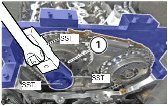
Tighten the intake camshaft timing gear bolt assembly.
- Torque:
1st 10 N*m (102 kgf*cm, 7 ft.*lbf) 2nd 30 N*m (306 kgf*cm, 22 ft.*lbf) 3rd 50 N*m (510 kgf*cm, 37 ft.*lbf)
- HINT:
-
Calculate the torque wrench reading when changing the fulcrum length of the torque wrench.
-
Click hereGeneral>INTRODUCTION>REPAIR INSTRUCTION>PRECAUTION
Using a digital angle torque wrench, tighten the intake camshaft timing gear bolt assembly an additional 35°.
- HINT:
- ·
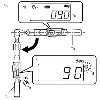 2.5,1.542 2.5,1.208 false 0.49,2.969 0.281,3.208 false 0.135,0.115 0.448,0.271 0.313,0.156 10 false *a 2.448,1.583 2.76,1.74 0.313,0.156 10 false *b 0.177,3.229 0.49,3.385 0.313,0.156 10 false *c 0.771,0.156 1.083,0.313 0.313,0.156 10 false *d 2.49,0.448 2.802,0.604 0.313,0.156 10 false *e 1.229,2 1.542,2.156 0.313,0.156 10 false *f 3.104,2.406 3.417,2.563 0.313,0.156 10 false *g 0.938,2.927 1.25,3.083 0.313,0.156 10 false *h
*a Example *b Before Tightening *c After Tightening *d Set Angle Display *e Setting the Specified Angle *f Tightening Angle Display *g LED Notification *h Buzzer Notification
·When using the digital angle torque wrench, set the wrench to the specified tightening angle before use.
·When using the digital angle torque wrench, check the tightening angle display while performing the work.
·When tightening reaches the set angle, the buzzer will sound and a blue LED will illuminate.
135A0A
7.FULLY TIGHTEN EXHAUST CAMSHAFT TIMING GEAR BOLT ASSEMBLY
To tighten the exhaust camshaft timing gear bolt assembly (1) use the special tool 2 450 487 .
- SST
- 09200-WA470
09200-WA800
09900-WA280
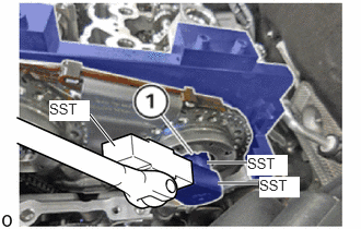
Tighten the exhaust camshaft timing gear bolt assembly (1).
- Torque:
1st 10 N*m (102 kgf*cm, 7 ft.*lbf) 2nd 30 N*m (306 kgf*cm, 22 ft.*lbf) 3rd 50 N*m (510 kgf*cm, 37 ft.*lbf)
- HINT:
-
Calculate the torque wrench reading when changing the fulcrum length of the torque wrench.
-
Click hereGeneral>INTRODUCTION>REPAIR INSTRUCTION>PRECAUTION
Using a digital angle torque wrench, tighten the exhaust camshaft timing gear bolt assembly an additional 35°.
- HINT:
- ·
2.5,1.542 2.5,1.208 false 0.49,2.969 0.281,3.208 false 0.135,0.115 0.448,0.271 0.313,0.156 10 false *a 2.448,1.583 2.76,1.74 0.313,0.156 10 false *b 0.177,3.229 0.49,3.385 0.313,0.156 10 false *c 0.771,0.156 1.083,0.313 0.313,0.156 10 false *d 2.49,0.448 2.802,0.604 0.313,0.156 10 false *e 1.229,2 1.542,2.156 0.313,0.156 10 false *f 3.104,2.406 3.417,2.563 0.313,0.156 10 false *g 0.938,2.927 1.25,3.083 0.313,0.156 10 false *h
*a Example *b Before Tightening *c After Tightening *d Set Angle Display *e Setting the Specified Angle *f Tightening Angle Display *g LED Notification *h Buzzer Notification
·When using the digital angle torque wrench, set the wrench to the specified tightening angle before use.
·When using the digital angle torque wrench, check the tightening angle display while performing the work.
·When tightening reaches the set angle, the buzzer will sound and a blue LED will illuminate.
8.REMOVE SST
13540
9.INSTALL NO. 1 CHAIN TENSIONER ASSEMBLY
10.INSPECT AND ADJUST CAMSHAFT SUB-ASSEMBLY
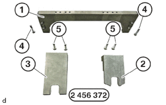
Have the set of special tools 2 456 372 ready.
| Number | Description |
|---|---|
| 1 | Basic carrier |
| 2 | 0.7° setting gauge to adjust the intake camshaft |
| 3 | 0.5° setting gauge to adjust the exhaust camshaft |
| 4 | Basic carrier screws on cylinder head |
| 5 | Screw gauge on basic carrier |
- SST
- 09200-WA700
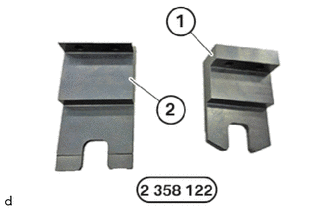
Keep the test gauge from the set of special tools 2 358 122 ready.
| Number | Description |
|---|---|
| 1 | Test gauge to fix the intake camshaft |
| 2 | Test gauge to fix the exhaust camshaft |
- SST
- 09200-WA380
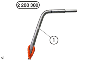
Have the special tool 2 288 380 ready.
| Number | Description |
|---|---|
| 1 | Alignment pin |
- SST
- 09200-WA570
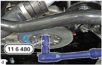
Turn the engine with the special tool 0 493 380 (11 6 480) to the TDC firing position of cylinder 1.
- SST
- 09200-WA190
- NOTICE:
- ·
Damage to the engine.
·The engine may be damaged if it is manually rotated in the wrong direction.
-Always rotate the engine in the correct direction of rotation by hand) Clockwise, facing the vibration damper or) Counter-clockwise, facing the chain drive. Only applies when the rear timing chain is installed.
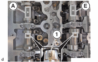
Make sure that the marks (1) on the intake camshaft sub-assembly (E) and the exhaust camshaft sub-assembly (A) are legible from above.
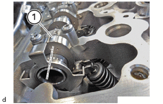
Ensure that the cam (1) on the exhaust camshaft sub-assembly on cylinder 1 points to the inside right at a slight angle.
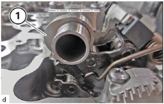
Ensure that the cam (1) on the intake camshaft sub-assembly on cylinder 1 points to the inside left at an angle.
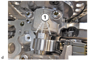
Ensure that the flattened areas (1) on the intake camshaft sub-assembly and the exhaust camshaft sub-assembly point upwards.
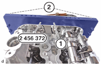
Position the basic carrier (1) from the set of special tools 2 456 372 on the cylinder head sub-assembly.
- SST
- 09200-WA700
Tighten the screws (2) from the set of special tools 2 456 372.
- SST
- 09200-WA700
- Torque:
- 8.0 N*m (82 kgf*cm, 71 in.*lbf)
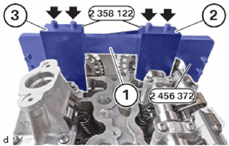
Position the test gauge (2) from the set of special tools 2 358 122 between the intake camshaft sub-assembly and the basic carrier (1) from the set of special tools 2 456 372.
- SST
- 09200-WA380
09200-WA700
Position the test gauge (3) from the set of special tools 2 358 122 between the exhaust camshaft sub-assembly and the basic carrier (1) from the set of special tools 2 456 372.
- SST
- 09200-WA380
09200-WA700
Tighten screws (arrows).
- Torque:
- 8.0 N*m (82 kgf*cm, 71 in.*lbf)
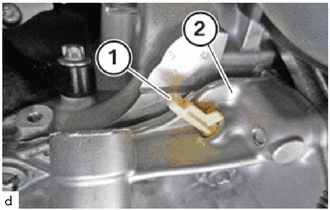
Guide out and remove sealing cap (1) on oil pan cover (2).
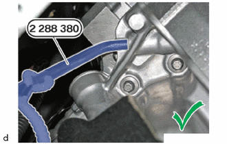
Position the special tool 2 288 380 correctly in the dowel hole.
- SST
- 09200-WA570
- HINT:
-
The engine is in the TDC firing position of cylinder 1.
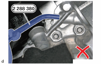
Make sure that the special tool 2 288 380 is not positioned incorrectly.
- SST
- 09200-WA570
- HINT:
-
The TDC firing position of cylinder 1 was not reached.
11.REMOVE SST
11201
12.INSTALL CYLINDER HEAD COVER SUB-ASSEMBLY
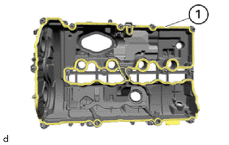
Type A:
Replace the cylinder head cover gasket (1).
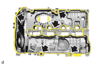
Type B:
Replace the cylinder head cover gasket as shown in the illustration.
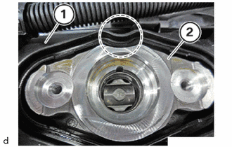
Ensure that the cylinder head cover sub-assembly (1) is installed in the marked area correctly on the fuel pump bracket (2).
- NOTICE:
-
The cylinder head cover sub-assembly (1) must not touch the high pressure pump bracket (2) in the marked area.
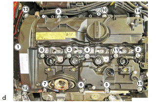
Position cylinder head cover sub-assembly.
Make sure that the cylinder head cover sub-assembly does not touch the fuel pump bracket.
Apply all E10 bolts of the cylinder head cover sub-assembly in the sequence (1) to (15) in 180° steps.
Tighten the E10 bolts of the cylinder head cover sub-assembly in sequence (1) to (15).
- Torque:
1st 8.0 N*m (82 kgf*cm, 71 in.*lbf) 2nd 10 N*m (102 kgf*cm, 7 ft.*lbf)
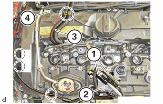
Position the No. 2 fuel pipe sub-assembly and tighten the bolts (4).
- Torque:
- 7.0 N*m (71 kgf*cm, 62 in.*lbf)
Position the engine wiring harness (3) and secure it.
Secure cable.
Position the carrier plate and tighten the bolt (2).
- Torque:
- 6.0 N*m (61 kgf*cm, 53 in.*lbf)
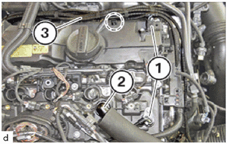
Secure both oxygen sensor connectors (1) on the carrier plate.
Correctly route the engine wiring harness (3) and secure it.
Connect the ventilation hose (2).
Connect both connectors (1).
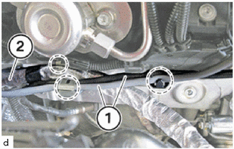
Secure the positive battery cable (2) in the marked area.
Attach both oxygen sensor cables (1) in the highlighted areas.
23250
13.INSTALL FUEL INJECTOR ASSEMBLY
23100X
14.INSTALL FUEL (ENGINE ROOM SIDE) PUMP ASSEMBLY
23802B
15.INSTALL NO. 2 FUEL PIPE SUB-ASSEMBLY
23801P
16.INSTALL NO. 1 FUEL PIPE SUB-ASSEMBLY
17.INSTALL SPARK PLUG
15370J
18.INSTALL CAM TIMING OIL CONTROL SOLENOID ASSEMBLY
17111
19.INSTALL INTAKE MANIFOLD
23285A
20.INSTALL NO. 1 CHECK VALVE
21.INSTALL ENGINE ROOM ECM BOX
22.INSTALL INTEGRATION RELAY (for Engine Room Side)
55789B
23.INSTALL NO. 2 COWL TOP VENTILATOR LOUVER PROTECTOR
24.INSTALL SEALING FRAME
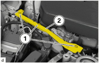
Feed in sealing frame (2).
Tighten the T25 screws (1).
- Torque:
- 2.5 N*m (25 kgf*cm, 22 in.*lbf)
55788A
25.INSTALL COWL TOP VENTILATOR LOUVER PROTECTOR
53681
26.INSTALL UPPER FRONT SUSPENSION CENTER BRACE
11271A
27.INSTALL REAR CYLINDER BLOCK COVER
11401T
28.INSTALL CYLINDER BLOCK COVER
53896B
29.INSTALL FRONT FENDER SPLASH FRONT SHIELD LH
53895B
30.INSTALL FRONT FENDER SPLASH FRONT SHIELD RH
- HINT:
-
Use the same procedure as for the LH side.
51410
31.INSTALL NO. 1 ENGINE UNDER COVER ASSEMBLY
17882
32.INSTALL NO. 2 AIR CLEANER HOSE
33.INSTALL NO. 2 CYLINDER BLOCK SIDE COVER
Feed in No. 2 cylinder block side cover.
Install the clip.
Tighten down T25 screw.
- Torque:
- 8.0 N*m (82 kgf*cm, 71 in.*lbf)
12601B
34.INSTALL NO. 1 ENGINE COVER SUB-ASSEMBLY
35.CONNECT CABLE TO NEGATIVE BATTERY TERMINAL
36.ADD ENGINE COOLANT (for Low Temperature)
37.ADD ENGINE OIL
12180E
38.INSTALL OIL FILLER CAP ASSEMBLY
39.INSPECT FOR COOLANT LEAK (for Low Temperature)
40. CHECK ENGINE OIL LEVEL
41.REMOVE AND INSTALL HOOD SUPPORT ASSEMBLY