B58 ENGINE MECHANICAL CAMSHAFT REMOVAL
CAUTION / NOTICE / HINT
- CAUTION:
- ·
Hot surfaces.
Risk of burning!
-Perform all work only on components that have cooled down.
- CAUTION:
- ·
Working on 12 V vehicle electrical system.
Risk of short circuits! Risk of fire!
-Detach battery earth lead from battery.
-For an auxiliary battery: Disconnect battery earth lead of auxiliary battery.
- NOTICE:
- ·
Damage to battery terminal, the safety battery terminal or the intelligent battery sensor (IBS).
Damaged battery terminals can lead to malfunctions or vehicle electrical system faults.
-Pull off battery terminal from battery pole by carefully moving to and fro. Do not pry off using a tool.
PROCEDURE

 13050
1.REMOVE CAMSHAFT TIMING GEAR ASSEMBLY
13070A
2.REMOVE CAMSHAFT TIMING EXHAUST GEAR ASSEMBLY
15330G
3.ADJUST SERVO MOTOR
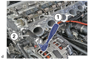
Using 4 mm hexagon wrench, Use servo motor (2) to adjust No. 3 camshaft sub-assembly (1) slowly to minimum lift.
4.INSPECT AND ADJUST CAMSHAFT
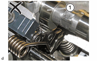
Check position of the intake camshaft sub-assembly on the respective cylinders.
Cam (1) of the intake camshaft sub-assembly runs on the intermediate lever.
Continue to turn the engine at the crankshaft pulley assembly with the special tool 0 493 380 (11 6 480) in the direction of engine rotation.
- SST
- 09200-WA190
5.INSPECT AND ADJUST CAMSHAFT (CYLINDERS 3 AND 4)
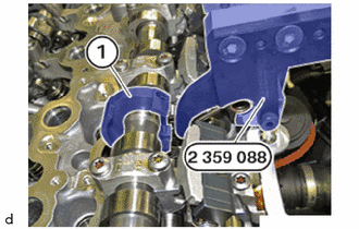
Check the position of the intake camshaft sub-assembly at cylinders 3 and 4.
To remove the torsion spring on cylinder 3 and 4 the camshaft sensor wheel (1) of the intake camshaft sub-assembly must be positioned as shown.
Camshaft sensor wheel (1) of the intake camshaft sub-assembly is not in the indicated position.
Turn engine on the crankshaft pulley assembly using special tool 0 493 380 (11 6 480) till the camshaft sensor wheel (1) of the intake camshaft sub-assembly is positioned as shown.
- SST
- 09200-WA190
6.REMOVE TORSION SPRING
- CAUTION:
- ·
Spring preload.
Danger of injury!
-The use of the specified special tool (tool) is mandatory.
-The described operation must be carried out properly.
-Wear safety goggles.
- NOTICE:
-
The description is for one component only. The procedure is identical for all further components.
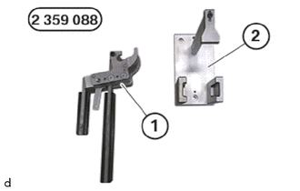
Have the set of special tools 2 359 088 ready.
- SST
- 09200-WA410
| Number | Description |
| 1 | Clamping lever |
| 2 | Mounting for clamping lever (fitting aid) |
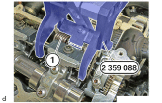
Open the special tool 2 359 088 and position it at the torsion spring (1).
- SST
- 09200-WA410
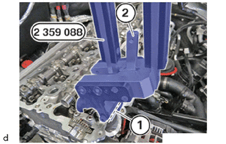
Make sure that the special tool 2 359 088 lies flat against the cylinder head in area (1).
- SST
- 09200-WA410
Carefully close the clamping lever of the special tool 2 359 088 until the retaining hook (2) engages.
- SST
- 09200-WA410
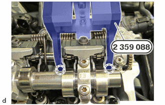
Check if the special tool 2 359 088 is positioned correctly on the torsion spring.
- SST
- 09200-WA410
Special tool 2 359 088 is not positioned correctly on the torsion spring.
- SST
- 09200-WA410
Carefully release the clamping lever of the special tool 2 359 088 and repeat the process.
- SST
- 09200-WA410
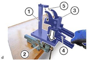
Clamp fixture (1) of the special tool 2 359 088 in the vice (2).
- SST
- 09200-WA410
Position clamping lever (3) of special tool 2 359 088 with pre-tensioned torsion spring (5) in direction of arrow in the mounting (1) of the special tool 2 359 088.
- SST
- 09200-WA410
Carefully unlock retaining hook (4) of the special tool 2 359 088.
- SST
- 09200-WA410
The torsion spring (5) is relieved.
Slowly open clamping lever (3) and remove the torsion spring (5).
Repeat the operations for the remaining torsion spring.
13908A
7.REMOVE GATE
13800
8.REMOVE INTERMEDIATE LEVER
9.REMOVE SST
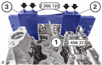
Remove bolts (arrows).
Guide the test gauge (2) out of the set of special tools 2 358 122 between the intake camshaft sub-assembly and the basic carrier (1) of the set of special tools 2 456 372 and remove.
- SST
- 09200-WA380
09200-WA700
Guide the test gauge (3) out of the set of special tools 2 358 122 between the exhaust camshaft and the basic carrier (1) of the set of special tools 2 456 372 and remove.
- SST
- 09200-WA380
09200-WA700
13501A
10.REMOVE INTAKE CAMSHAFT SUB-ASSEMBLY
- NOTICE:
- ·
Contaminant or foreign body.
Contamination can result in malfunctions, operating failure or leaks.
-Adhere to the utmost cleanliness.
-Protect components from contamination e.g. by covering.
-Close off line connections with seal plugs.
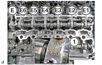
Observe the numbering (1) of the camshaft bearing caps.
The camshaft bearing caps are numbered from (E1) to (E6).
The camshaft bearing cap (E) is a thrust bearing.
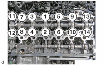
Release T30 bolts in the right sequence (14) till (1) in semi circle pattern.
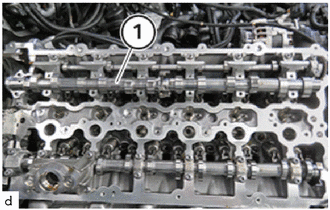
Guide out intake camshaft sub-assembly (1) toward the top and remove it.
11.REMOVE CAMSHAFT SENSOR WHEEL
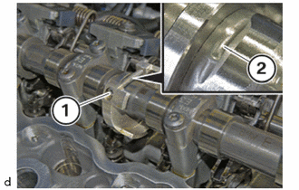
Rotate intake camshaft sub-assembly, if necessary in the position shown.
The recess (2) must point upwards.
Using 3 mm hexagon wrench, Loosen bolt (1).
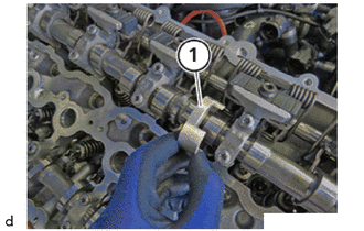
Slide camshaft sensor wheel (1) in the direction of cylinder 1 and guide it out from the intake camshaft sub-assembly.
13502B
12.REMOVE EXHAUST CAMSHAFT SUB-ASSEMBLY
- NOTICE:
- ·
Contaminant or foreign body.
Contamination can result in malfunctions, operating failure or leaks.
-Adhere to the utmost cleanliness.
-Protect components from contamination e.g. by covering.
-Close off line connections with seal plugs.
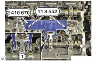
Position the special tool 2 410 670 at cylinder 2 and apply it hand-tight with the special tool 0 495 741 (11 8 552) from the set of special tools 0 495 739 (11 8 550).
- SST
- 09200-WA500
09200-WA510
Bolt in both roller cam followers (1) on the 2nd cylinder using the spindle nut of the special tool 2 410 670 up to the limit position.
- SST
- 09200-WA500
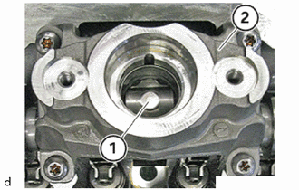
Remove fuel pump lifter assembly (1) from exhaust camshaft bearing cap (2).
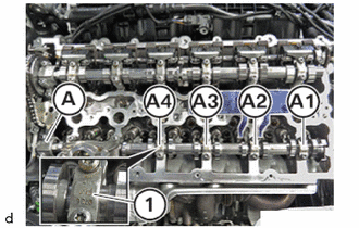
Observe the numbering of the exhaust camshaft bearing caps.
The exhaust camshaft bearing caps are numbered from (A1) to (A4) and are laid down according to their numbering.
The exhaust camshaft bearing cap (A) is a thrust bearing.
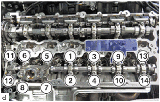
Release T30 bolts in the right sequence (14) till (1) in semi circle pattern.
Guide out and remove the exhaust camshaft bearing caps.
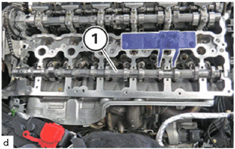
Guide out exhaust camshaft sub-assembly (1) upwards and remove it.