B58 ENGINE MECHANICAL CYLINDER HEAD DISASSEMBLY
CAUTION / NOTICE / HINT
PROCEDURE

 11115
1.REMOVE CYLINDER HEAD GASKET
17201
2.REMOVE TURBOCHARGER SUB-ASSEMBLY
13053
3.ADJUST NO. 3 CAMSHAFT SUB-ASSEMBLY
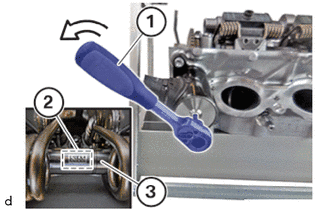
With the help of the servo motor, use a 4 mm hexagon socket wrench (1) to slowly adjust No. 3 camshaft sub-assembly (3) to the minimum lift at 4 mm in the direction of the arrow.
Make sure that the mark (2) on the No. 3 camshaft sub-assembly (3) points upwards.
4.INSPECT AND ADJUST CAMSHAFT
5.INSPECT AND ADJUST CAMSHAFT (CYLINDERS 3 AND 4)
6.REMOVE TORSION SPRING
- CAUTION:
- ·
Spring preload.
Danger of injury!
-The use of the specified special tool (tool) is mandatory.
-The described operation must be carried out properly.
- HINT:
-
Wear safety goggles.
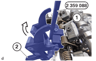
Open the special tool 2 359 088 and position it at the torsion spring (1).
- SST
- 09200-WA410
Position retaining hook (2) of the special tool 2 359 088 in the direction of arrow.
- SST
- 09200-WA410
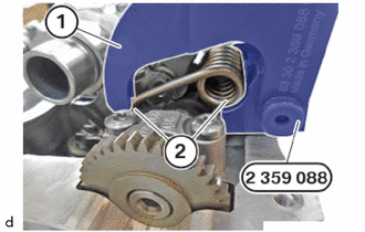
Make sure that the torsion spring (2) is correctly positioned in the clamping lever (1) of the special tool 2 359 088 .
- SST
- 09200-WA410
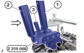
Hold down lever (1) of special tool 2 359 088 .
- SST
- 09200-WA410
Close lever (2) of the special tool 2 359 088 carefully in the direction of arrow until the retaining hook (3) engages audibly.
- SST
- 09200-WA410
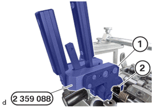
Thread out clamping lever (1) of special tool 2 359 088 with pre-tensioned torsion spring (2)carefully then remove.
- SST
- 09200-WA410
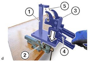
Clamp fixture (1) of the special tool 2 359 088 in the vice (2).
- SST
- 09200-WA410
Position clamping lever (3) of special tool 2 359 088 with pre-tensioned torsion spring (5) in direction of arrow in the mounting (1) of the special tool 2 359 088 .
- SST
- 09200-WA410
Carefully unlock retaining hook (4) of the special tool 2 359 088 .
The torsion spring (5) is relieved.
- SST
- 09200-WA410
Slowly open clamping lever (3) and remove the torsion spring (5).
Repeat the operations for the remaining torsion spring.
13908A
7.REMOVE GATE
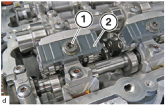
Loosen T40 bolts (1).
Remove the gate (2).
Repeat the step for all the gate.
13800
8.REMOVE INTERMEDIATE LEVER
13501A
9.REMOVE INTAKE CAMSHAFT SUB-ASSEMBLY
15330G
10.REMOVE CAM TIMING OIL CONTROL SOLENOID ASSEMBLY
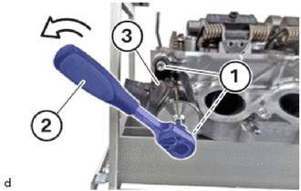
Loosen T30 bolts (1).
Using a 4 mm hexagon wrench (2), turn servo motor for the No. 3 camshaft sub-assembly (3) to the left on the bolt in the marked area and pull off the cylinder head at the same time.
- NOTICE:
-
Do not turn the No. 3 camshaft sub-assembly beyond the end stop.
- HINT:
-
This releases the tension of the eccentric shaft.
Removing the servo motor for the eccentric shaft (3).
13053
11.REMOVE NO. 3 CAMSHAFT SUB-ASSEMBLY
13502B
12.REMOVE EXHAUST CAMSHAFT SUB-ASSEMBLY
13801
13.REMOVE NO.1 VALVE ROCKER ARM SUB-ASSEMBLY
13750
14.REMOVE VALVE LASH ADJUSTER ASSEMBLY
15.REMOVE INTAKE VALVE COMPRESSION SPRING
16.REMOVE EXHAUST VALVE COMPRESSION SPRING
17.REMOVE VALVE STEM OIL SEAL
13711
18.REMOVE INTAKE VALVE
13715
19.REMOVE EXHAUST VALVE