STEERING GEAR / LINKAGE STEERING GEAR INSTALLATION
CAUTION / NOTICE / HINT
- HINT:
- ·
Use the same procedure for LHD and RHD vehicles.
·The procedure listed below is for the LHD vehicles.
PROCEDURE

 1.INSTALL STEERING LINK ASSEMBLY
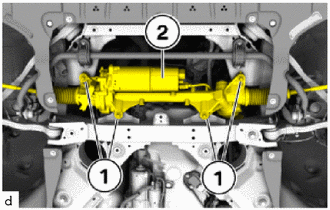
Install the steering link assembly (2).
Replace the E14 bolts (1) and 18 mm nuts.
Tighten the E14 bolts (1). In this process, counter support at the 18 mm nuts.
- Torque:
- 100 N*m (1020 kgf*cm, 74 ft.*lbf)
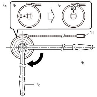
Using SST, tighten the E14 bolts (1) an additional 90°.
- SST
- 09900-WA010
- HINT:
-
 2.99,1.271 3.156,1.188 false 2.906,2.094 2.906,1.76 false 0.875,3 1.208,3 false 0.104,0.125 0.417,0.281 0.313,0.156 10 false *a 0.448,0.125 0.76,0.281 0.313,0.156 10 false *b 2.042,0.125 2.354,0.281 0.313,0.156 10 false *c 3.188,1.073 3.427,1.271 0.24,0.198 10 false *d 2.854,2.146 3.167,2.302 0.313,0.156 10 false *b 1.302,2.927 1.615,3.083 0.313,0.156 10 false *c
*a Example *b Before Tightening *c After Tightening *d Magnetic Portion
- ·
The magnetic portion is used to secure the gauge to the vehicle.
·After first adjusting the needle of the gauge to 0°, tighten to the specified angle.
·Perform the work procedure carefully so that the gauge, etc. does not become tilted.
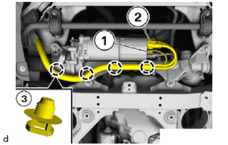
for LHD:
Connect connectors (1) and (2) and lock.
Clip the wiring harness into the holder (3).
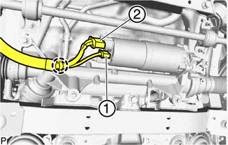
for RHD:
Connect connectors (1) and (2) and lock.
Engage the wiring harness clamp.
45220
2.CONNECT STEERING INTERMEDIATE SHAFT ASSEMBLY
- HINT:
- ·
The steering intermediate shaft assembly can only be installed in one position.
·The steering intermediate shaft assembly is encoded for the steering column and the steering gear. The clamping bolt must be positioned in the groove of the steering gear or the steering column.
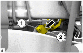
Slide the steering intermediate shaft assembly (2) in the direction of the arrow onto the steering gear assembly.
Replace the E10 bolt (1).
Tighten down E10 bolt (1).
- Torque:
- 28 N*m (286 kgf*cm, 21 ft.*lbf)
45047
3.CONNECT TIE ROD END SUB-ASSEMBLY LH
Install the tie rod end sub-assembly LH on the steering knuckle LH.
Replace nut.
Tighten the nut.
- Torque:
- 165 N*m (1683 kgf*cm, 122 ft.*lbf)
- HINT:
-
If necessary, counter support the T40 "TORX" socket wrench.
45046
4.CONNECT TIE ROD END SUB-ASSEMBLY RH
- HINT:
-
Perform the same procedure as for the LH side.
51219
5.INSTALL FRONT SUSPENSION MEMBER LOWER PROTECTOR
6.INSTALL FRONT WHEELS
7.INSPECT AIRBAG FOR FUNCTION
8. ENCODE/PROGRAM CONTROL UNIT(S)
- NOTICE:
- ·
Use the most recent software version to prevent faults during programming/encoding.
·The battery voltage must not drop below 13.0 V during programming.
·Use only recommended chargers for a low-voltage vehicle electrical system.
·Do not exceed the maximum charging voltage of 14.8 V when charging the battery.
·When there is communication abnormality in the middle of work, control unit might be damaged.
·It may be necessary to perform the Action Plan several times.
Connect the battery charger to the vehicle.
Connect the diagnosis system with the vehicle.
Determine the action plan.
Service plan / Programming plan / Action plan / Calculate action plan
Accept and fully process the measures plan.
Service plan / Programming plan / Action plan / Perform action plan
Wait until programming/encoding has been completed.
- NOTICE:
-
When there is communication abnormality in the middle of work, control unit might be damaged.
Carry out vehicle test.
Vehicle management / Troubleshooting / Fault memory / Calculate test plan
Delete the fault memory.
Vehicle management / Troubleshooting / Fault memory / Delete fault memory
Disconnect the diagnosis system from the vehicle.
Disconnect the battery charger from the vehicle.
9. START-UP OF ELECTROMECHANICAL STEERING
10.INSPECT AND ADJUST FRONT WHEEL ALIGNMENT