ALIGNMENT / HANDLING DIAGNOSIS FRONT WHEEL ALIGNMENT ADJUSTMENT
CAUTION / NOTICE / HINT
- NOTICE:
-
Before inspecting the wheel alignment, adjust the vehicle height to the specified value.
- HINT:
-
Camber and toe-in influence each other. Adjust the toe-in first in order to simplify the adjustment procedure.
PROCEDURE

 1.INSPECT TIRES
2. PREPARATION FOR INSPECTION AND ADJUSTMENT
- NOTICE:
- ·
Before inspecting the wheel alignment, adjust the vehicle height to the specified value.
·Be sure to perform measurement on a level surface.
·If it is necessary to go under the vehicle for measurement, confirm that the parking brake is applied and the vehicle is secured with chocks.
Check vehicle interior and luggage compartment for load status, if applicable, unload vehicle.
Place specified load into the vehicle.
Driver seat center position: 68 kg (149.9 lb)
Passenger seat center position: 68 kg (149.9 lb)
Luggage compartment center position: 14 kg (30.9 lb)
Fuel tank: full tank
Position weights in the luggage compartment until the nominal ride-level height of the vehicle is reached.
Position weights in the footwell as far as possible in the direction of front axle until the nominal ride-level height of the vehicle is reached.
Measure the vehicle height.
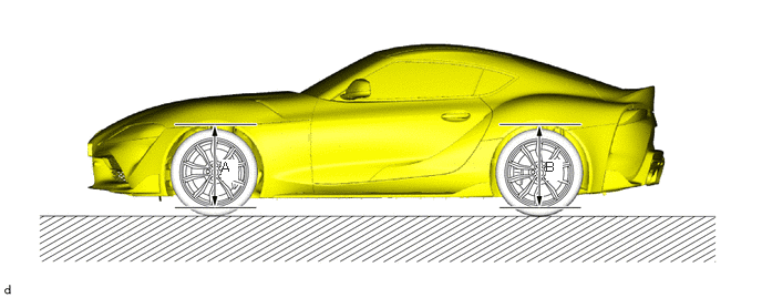
- Vehicle Height:
Tire Size Equipment Front (A) Rear (B) 17 inch w/o AVS 610 mm (2.00 ft.) 607 mm (1.99 ft.) w/ AVS 602 mm (1.97 ft.) 599 mm (1.96 ft.) 18 inch w/o AVS 621 mm (2.04 ft.) 619 mm (2.03 ft.) w/ AVS 614 mm (2.01 ft.) 612 mm (2.01 ft.) 19 inch w/o AVS 634 mm (2.08 ft.) 632 mm (2.07 ft.) w/ AVS 627 mm (2.06 ft.) 625 mm (2.05 ft.)
- NOTICE:
- ·
Height is measured vertically through wheel center from lower rim flank to wheel arch edge.
·The tolerance for the vehicle height is 2 mm (0.0787 in.) or less.
·The difference between the left and right is 2 mm (0.0787 in.) or less.
3.INSPECT TOE-IN
Bounce the vehicle up and down at the corners to stabilize the suspension.
Release the parking brake and move the shift position to N.
Push the vehicle straight ahead approximately 5 m (16.4 ft.). (Step C)
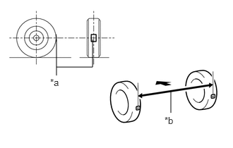
| *a | Tread Center Mark |
| *b | Dimension B |

|
Front of the Vehicle |
Put tread center marks on the rearmost points of the front wheels and measure the distance between the marks (dimension B).
Slowly push the vehicle straight ahead to cause the front wheels to rotate 180°. Use the front tire valve as a reference point.
- HINT:
-
Do not allow the wheels to rotate more than 180°. If the wheels rotate more than 180°, perform the procedure from step C again.
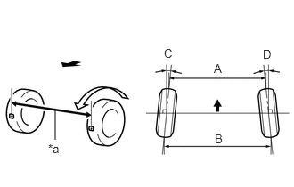
| *a | Dimension A |
|
|
Front of the Vehicle |
Measure the distance between the tread center marks on the front of the wheels (dimension A).
- Toe-in:
Specified Condition C + D: 0°16' +/- 0°12' (0.27° +/- 0.20°) B - A: 3.1 +/- 2.3 mm (0.1220 +/- 0.0906 in.)
- HINT:
-
Measure "B - A" only when "C + D" cannot be measured.
4.ADJUST TOE-IN
- HINT:
-
Camber and toe-in influence each other. Adjust the toe-in first in order to simplify the adjustment procedure.
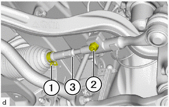
Separate the steering rack boot clips (1) from the steering rack boot.
Loosen the T50 lock bolts (2) on the tie rod end.
Turn the right and left tie rods (3) by an equal amount to adjust the toe-in.
Tighten the T50 lock bolts (2) on the tie rod end.
- Torque:
- 32 N*m (326 kgf*cm, 24 ft.*lbf)
Place the steering rack boots on the seats and install the steering rack boot clips (1).
- HINT:
-
Make sure that the steering rack boots are not twisted.
5.INSPECT CAMBER, CASTER AND STEERING AXIS INCLINATION
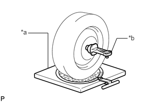
| *a | Turning Radius Gauge |
| *b | Camber-caster-kingpin Gauge |
Install a camber-caster-kingpin gauge and place the front wheels on the center of a turning radius gauge.
Inspect the camber, caster and steering axis inclination.
- Camber:
Equipment Camber Inclination Right-left Difference w/o AVS -1°38' +/- 0°30' (-1.63° +/- 0.50°) 0°30' (0.50°) or less w/ AVS -1°45' +/- 0°30' (-1.75° +/- 0.50°)
- Caster:
Caster Inclination Right-left Difference 7°35' +/- 0°30' (7.58° +/- 0.50°) 0°30' (0.50°) or less
- Steering Axis Inclination:
Steering Axis Inclination Reference 17°21' (17.35°)
6.ADJUST CAMBER
- HINT:
-
Camber and toe-in influence each other. Adjust the toe-in first in order to simplify the adjustment procedure.
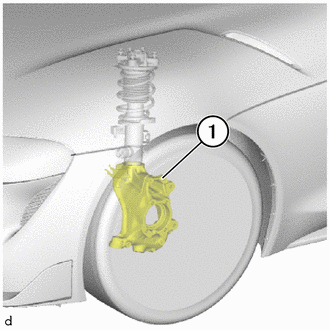
Adjust camber by changing steering knuckle (1) to service steering knuckle.
- Service Steering Knuckle:
Position Toyota Part No.
(BMW Part No.)Correction Value LH side 43212-WAA01
(6 878 613)Standard 43212-WAA02
(6 877 201)-30' (-0.50°) 43212-WAA03
(6 877 203)+30' (+0.50°) RH side 43211-WAA01
(6 878 614)Standard 43211-WAA02
(6 877 202)-30' (-0.50°) 43211-WAA03
(6 877 204)+30' (+0.50°)
Remove the steering knuckle.
Click hereDrivetrain>AXLE AND DIFFERENTIAL>STEERING KNUCKLE>REMOVAL
Install the service steering knuckle.
Click hereDrivetrain>AXLE AND DIFFERENTIAL>STEERING KNUCKLE>INSTALLATION
7.INSPECT WHEEL ANGLE
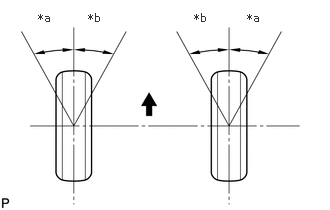
| *a | Inside |
| *b | Outside |
|
|
Front of the Vehicle |
Put tread center marks on the rearmost points of a turning radius gauge.
Turn the steering wheel fully to the left and right and measure the turning angle.
- Wheel Turning Angle:
Inside Wheel Outside Wheel 38°23' (38.38°) 29°09' (29.15°)
If the right and left inside wheel angles differ from the specified value, check and adjust the right and left tie rod lengths.
8. START-UP OF ELECTROMECHANICAL STEERING