STEERING GEAR / LINKAGE TIE ROD INSTALLATION
CAUTION / NOTICE / HINT
- HINT:
- ·
Use the same procedure for the RH side and LH side.
·The following procedure is for the LH side.
PROCEDURE

 45470
1.INSTALL TIE ROD ASSEMBLY
- NOTICE:
-
In order to avoid damage of the steering shaft and its bearing, the steering shaft must be positioned in the steering gear as far as possible.
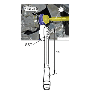
| *a | Torque Wrench Fulcrum Length |
Screw on and tighten the tie rod assembly to the steering shaft with the special tool 0 496 483 (32 3 220) and SST.
- SST
- 09600-WA040
09900-WA280
- Torque:
- 105 N*m (1071 kgf*cm, 77 ft.*lbf)
- HINT:
-
Calculate the torque wrench reading when changing the fulcrum length of the torque wrench.
-
Click hereGeneral>INTRODUCTION>REPAIR INSTRUCTION>PRECAUTION
45536
2.INSTALL STEERING RACK BOOT
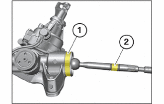
Coat the tie rod assembly in the illustration (1) and (2) with lubricating grease FB-1.
- HINT:
-
This ensures that the steering rack boot is not rotated when the tie rod assembly is rotated.
Push on the steering rack boot.
Attach the clip.
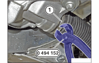
Replace clamp (1).
Attach the hook lock and press together the clamp (1) using special tool 0 494 152 (32 1 260).
- SST
- 09200-WA590
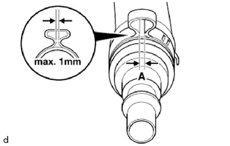
Check the clearance.
- Standard Measurement:
Area Measurement A Max. 1 mm (0.0393 in.)
45047
3.INSTALL TIE ROD END SUB-ASSEMBLY
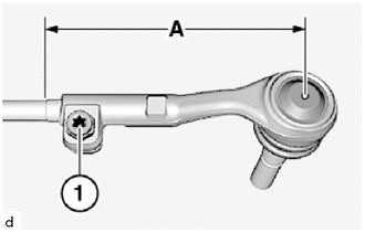
Screw the tie rod end sub-assembly onto the tie rod assembly until the dimension (A) is reached.
- HINT:
- ·
The dimension (A) was determined during the removal.
·If necessary, use an open-end spanner for counter support at the tie rod assembly.
Tighten down T50 bolt (1).
- Torque:
- 32 N*m (326 kgf*cm, 24 ft.*lbf)
Install the tie rod end sub-assembly on the steering knuckle.
Replace nut.
Tighten the nut.
- Torque:
- 165 N*m (1683 kgf*cm, 122 ft.*lbf)
- HINT:
-
If necessary, counter support the T40 "TORX" socket wrench.
51219
4.INSTALL FRONT SUSPENSION MEMBER LOWER PROTECTOR
5.INSTALL FRONT WHEEL
6.INSPECT AND ADJUST FRONT WHEEL ALIGNMENT