MAINTENANCE B48 COOLANT(for Low Temperature) REPLACEMENT
PROCEDURE

 51410
1.REMOVE NO. 1 ENGINE UNDER COVER ASSEMBLY
53896B
2.REMOVE FRONT FENDER SPLASH FRONT SHIELD LH
53895B
3.REMOVE FRONT FENDER SPLASH FRONT SHIELD RH
- HINT:
-
Use the same procedure as for the LH side.
4.DRAIN ENGINE COOLANT
- CAUTION:
- ·
Hot fluids.
Risk of scalding!
-Conduct all work in the vehicle wearing appropriate personal protective equipment only.
- NOTICE:
- ·
Life-long fill of coolant!
·Do not reuse used coolant.
When replacing and removing components which rely on the corrosion protection effect of the coolant, it is essential to change the coolant. The cooling system must therefore be emptied and refilled.
In the case of other removal work involving the draining of part quantities of coolant, the coolant level must be topped up with new coolant.
·Collect and dispose of emerging fluids. Observe country-specific waste disposal regulations.
Check that the START-STOP button (engine switch) off.
- HINT:
-
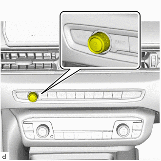
-
Pressing and holding the AUDIO button changes the power source mode to IG OFF.
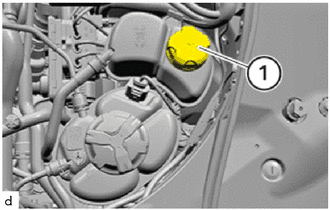
Loosen radiator reserve tank cap sub-assembly (1).
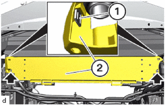
Remove T30 screws (arrows).
Unlock the locks (1).
Remove the radiator lower air guide plate (2) from the radiator assembly.
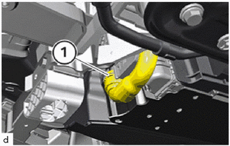
Unlock No. 6 radiator hose (1) on No. 2 radiator assembly for low-temperature cooling system and release.
Catch and dispose of escaping coolant.
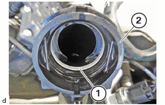
Check the sealing ring (1) of the No. 6 radiator hose (2) for damage and renew where required.
Connect No. 6 radiator hose on No. 2 radiator assembly for low-temperature cooling system and lock.
- HINT:
-
Make sure that the connections are locked correctly. The locks must engage audibly.
Install the radiator lower air guide plate to the radiator assembly.
The locks must engage audibly.
Tighten T30 screws (arrows).
- Torque:
- 6.0 N*m (61 kgf*cm, 53 in.*lbf)
5.ADD ENGINE COOLANT
- NOTICE:
- ·
Life-long fill of coolant!
·Do not reuse used coolant.
When replacing and removing components which rely on the corrosion protection effect of the coolant, it is essential to change the coolant. The cooling system must therefore be emptied and refilled.
In the case of other removal work involving the draining of part quantities of coolant, the coolant level must be topped up with new coolant.
·Mixing different coolants is not permitted.
Non-compliance will result in danger of component damage and/or engine damage.
·Filling specification absolutely must be adhered to.
The operation of the vehicle is not permitted unless the filling procedure has been completed. Otherwise,functional limitations (degradation) and/or overheating may occur.
A bleeding procedure is required after a part has been exchanged in the cooling system and/or after refilling the cooling system.
- HINT:
- ·
Before starting the automatic cooling system bleeding routine, make sure that all coolant circuits are filled. If the cooling system bleeding routine is started while one of the coolant circuits is empty, there is a risk of damage to the electric coolant pump when running it dry.
·Make sure that negative (-) battery terminal is not disconnected for the bleeding procedure. Switch on low-beam headlights and hazard warning lights. If the low-beam headlights and hazard warning lights are not switched on, the engine switch off automatically after a certain period of time and interrupt the bleeding procedure.
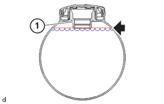
Add engine coolant to the level shown in the illustration.
- Standard Capacity:
4.0 liters (4.2 US qts, 3.5 Imp. qts)
Expendable materials : Antifreeze and Corrosion Inhibitor Frostox HT-12
- HINT:
-
When using Antifreeze and Corrosion Inhibitor Frostox HT-12, dilute the Antifreeze and Corrosion Inhibitor Frostox HT-12 to 50% before using it.
Ensure that the bonnet is open.
Connect battery charger.
- NOTICE:
-
For additional information see:
-
Click herePower Source / Network>B48 (BATTERY / CHARGING)>BATTERY>PRECAUTION
Press the START-STOP button (engine switch) 3 times within 0.8 seconds to enter Diagnostic (PAD) Mode.[*1]
Turn on low-beam headlight and the hazard warning light.[*2]
- HINT:
-
If the low-beam headlights and hazard warning lights are not switched on, the engine switch off automatically after a certain period of time and interrupt the bleeding procedure.
Adjust the heating to maximum temperature and adjust the blower to the lowest stage.[*3]
Hold the accelerator pedal down for at least 10 s at limit position and do not step onto the brake pedal.[*4]
Do not start engine.
The cooling system bleeding routine will start.[*5]
- HINT:
- ·
The electric water pump in the low-temperature coolant circuit is activated for 11 minutes according to a cooling system bleeding routine.
·The cooling system bleeding routine ends after 11 minutes.
·Observe the display in the instrument cluster (KOMBI).
While adding coolant to the reserve tank sub-assembly to keep the coolant at the maximum mark and compensate for the drop in the coolant level as the air bleeds.[*6]
- HINT:
-
If the service function is interrupted, the cooling system bleeding routine must be repeated.
If the engine coolant level is below the maximum mark, repeat steps [*1] through [*6] until the water level in the radiator reserve tank assembly stops decreasing.
Adjust the filling level in the radiator reserve tank sub-assembly of the low-temperature coolant circuit to 100 ml above the maximum mark.
Close radiator reserve tank cap sub-assembly.
- NOTICE:
- ·
After the cooling system bleeding routine, the cooling system is topped up above the maximum mark.
·Overfilling the cooling system serves to balance the remaining air in the cooling system.
·The normal filling level of the coolant is reached while driving.
Disconnect battery charger.
6.INSPECT FOR COOLANT LEAK
53896B
7.INSTALL FRONT FENDER SPLASH FRONT SHIELD LH
53895B
8.INSTALL FRONT FENDER SPLASH FRONT SHIELD RH
- HINT:
-
Use the same procedure as for the LH side.
51410
9.INSTALL NO. 1 ENGINE UNDER COVER ASSEMBLY