B58 INTAKE / EXHAUST TURBO CHARGER ACTUATOR AND LINK REMOVAL
CAUTION / NOTICE / HINT
- CAUTION:
- ·
Hot surfaces.
Risk of burning!
-Perform all work only on components that have cooled down.
- NOTICE:
-
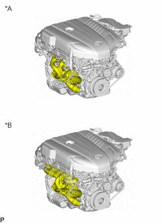 0.104,0.094 0.417,0.292 0.313,0.198 10 false *A 0.104,2.542 0.417,2.74 0.313,0.198 10 false *B
*A for 2 Port Type *B for 6 Port Type
-
Check the shape of the Turbo Charger SUB-ASSY before doing removal/installation work.
PROCEDURE

 17880
1.REMOVE AIR CLEANER HOSE ASSEMBLY
12261
2.REMOVE VENTILATION HOSE (for 2 Port Type)
17240
3.REMOVE TURBOCHARGER ACTUATOR AND LINK ASSEMBLY (for 2 Port Type)
- CAUTION:
- ·
Hot surfaces.
Risk of burning!
-Perform all work only on components that have cooled down.
- NOTICE:
- ·
Damage to the turbocharger actuator and link assembly and the mechanical connection.
Improper handling of the turbocharger actuator and link assembly can lead to malfunctions or failure of the turbocharger actuator and link assembly.
-Avoid exposure of lateral forces to the control rod of the turbocharger actuator and link assembly.
·Electrostatic discharge.
Damage to or destruction of electrical components.
-Only touch the housings of electrical components. Do not touch pins or multi-pin connectors directly.
-For additional information see:
Click hereGeneral>INTRODUCTION>REPAIR INSTRUCTION>PRECAUTION
- HINT:
-
It is not necessary to adjust the turbocharger actuator and link assembly after removing and installing or renewing.
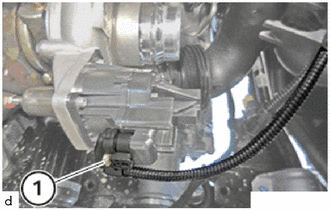
Unlock and loosen connector (1).
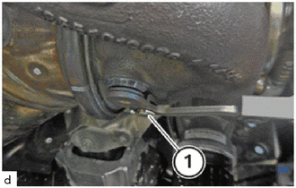
Unlock and detach retaining clip (1).
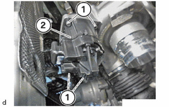
Loosen the T25 bolts (1) on the turbocharger actuator and link assembly (2).
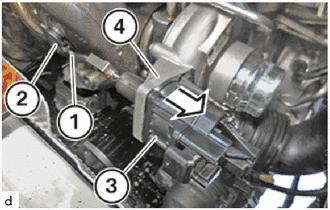
Guide the turbocharger actuator and link assembly (3) out of the compressor housing bore hole (4) in the direction of arrow and remove it.
- NOTICE:
- ·
Carefully pull the control rod (1) of the turbocharger actuator and link assembly (3) off the pin on the lever of the wastegate valve (2).
·Any effect of lateral force on the control rod (1) must be avoided.
17240
4.REMOVE TURBOCHARGER ACTUATOR AND LINK ASSEMBLY (for 6 Port Type)
- CAUTION:
- ·
Hot surfaces.
Risk of burning!
-Perform all work only on components that have cooled down.
- NOTICE:
- ·
Damage to the turbocharger actuator and link assembly and the mechanical connection.
Improper handling of the turbocharger actuator and link assembly can lead to malfunctions or failure of the turbocharger actuator and link assembly.
-Avoid exposure of lateral forces to the control rod of the turbocharger actuator and link assembly.
·Electrostatic discharge.
Damage to or destruction of electrical components.
-Only touch the housings of electrical components. Do not touch pins or multi-pin connectors directly.
-For additional information see:
Click hereGeneral>INTRODUCTION>REPAIR INSTRUCTION>PRECAUTION
- HINT:
-
It is not necessary to adjust the turbocharger actuator and link assembly after removing and installing or renewing.
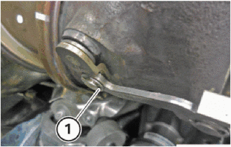
Unlock and detach retaining clip (1).
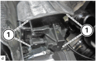
Release screws (1).
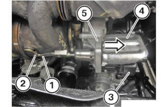
Feed out the electrical wastegate valve controller (3) with the heat shield (4) in the direction of the arrow from the bore hole of the compressor housing (5) and remove it.
- NOTICE:
- ·
Carefully pull the control rod (1) of the electrical wastegate valve controller (3) off the pin on the lever of the wastegate valve (2).
·Any effect of lateral force on the control rod (1) must be avoided.
Remove the heat shield (4).