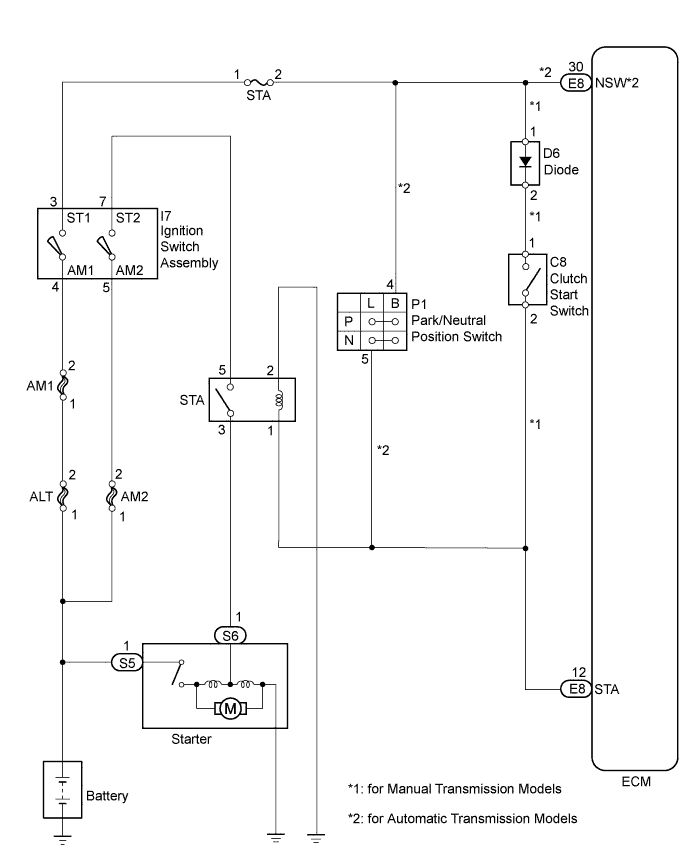
SFI SYSTEM > Starter Signal Circuit |
| 1.CHECK WHETHER ENGINE CAN BE CRANKED |
Check if the engine can be cranked.
| Result | Proceed to |
| Engine cannot be cranked | A |
| Engine can be cranked | B |
|
| ||||
| A | |
 |
| 2.READ VALUE USING TECHSTREAM (STARTER SIGNAL) |
Connect the Techstream to the DLC3.
Turn the ignition switch to ON.
Turn the Techstream on.
Enter the following menus: Powertrain / Engine and ECT / Data List / Starter Signal.
Check the value displayed on the Techstream when the ignition switch is turned to the ON and START positions.
| Ignition Switch Position | Starter Signal |
| ON | OFF |
| START | ON |
|
| ||||
| OK | |
|
| 3.INSPECT IGNITION SWITCH ASSEMBLY |
Inspect the ignition switch assembly (Click here).
|
| ||||
| OK | |
|
| 4.CHECK HARNESS AND CONNECTOR (IGNITION SWITCH ASSEMBLY - STA RELAY - STARTER) |
Remove the STA relay from the engine room relay block.
Disconnect the ignition switch assembly connector.
Disconnect the starter connector.
Measure the resistance according to the value(s) in the table below.
| Tester Connection | Condition | Specified Condition |
| I7-7 (ST2) - 5 (STA relay) | Always | Below 1 Ω |
| 3 (STA relay) - S6-1 (Starter) | Always | Below 1 Ω |
| Tester Connection | Condition | Specified Condition |
| I7-7 (ST2) or 5 (STA relay) - Body ground | Always | 10 kΩ or higher |
| 3 (STA relay) or S6-1 (Starter) - Body ground | Always | 10 kΩ or higher |
|
| ||||
| OK | |
|
| 5.CHECK HARNESS AND CONNECTOR (ECM - STA RELAY - BODY GROUND) |
Remove the STA relay from the engine room relay block.
Disconnect the ECM connector.
Measure the resistance according to the value(s) in the table below.
| Tester Connection | Condition | Specified Condition |
| E8-12 (STA) - 1 (STA relay) | Always | Below 1 Ω |
| 2 (STA relay) - Body ground | Always | Below 1 Ω |
|
| ||||
| OK | ||
 | ||
| ||
| 6.INSPECT IGNITION SWITCH ASSEMBLY |
Inspect the ignition switch assembly (Click here).
|
| ||||
| OK | |
|
| 7.INSPECT PARK/NEUTRAL POSITION SWITCH OR CLUTCH START SWITCH |
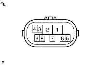 |
Inspect the park/neutral position switch (for automatic transmission models).
Disconnect the park/neutral position switch connector.
Measure the resistance of the park neutral position switch when the transmission gear selector lever is moved to each position.
| Tester Connection | Shift Lever Position | Specified Condition |
| 2 - 6, 4 - 5 | P | Below 1 Ω |
| 1 - 2 | R | Below 1 Ω |
| 2 - 9, 4 - 5 | N | Below 1 Ω |
| 2 - 7 | D | Below 1 Ω |
| 2 - 3 | 2 | Below 1 Ω |
| 2 - 8 | L | Below 1 Ω |
| *a | Component without harness connected (Park/Neutral Position Switch) |
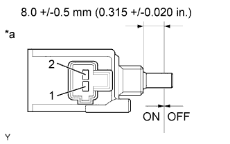 |
Inspect the clutch start switch (for manual transmission models).
Disconnect the clutch start switch connector.
Measure the resistance between the terminals when the clutch start switch is ON and OFF.
| Tester Connection | Switch Position | Specified Condition |
| 1 - 2 | ON (pushed) | Below 1 Ω |
| 1 - 2 | OFF (released) | 10 kΩ or higher |
| *a | Component without harness connected (Clutch Start Switch) |
| Result | Proceed to |
| OK | A |
| NG (for manual transmission models) | B |
| NG (for A340E automatic transmission models) | C |
| NG (for A340F automatic transmission models) | D |
|
| ||||
|
| ||||
|
| ||||
| A | |
|
| 8.CHECK HARNESS AND CONNECTOR (IGNITION SWITCH ASSEMBLY - PARK/NEUTRAL POSITION SWITCH OR CLUTCH START SWITCH) |
For automatic transmission models:
Disconnect the ignition switch assembly connector.
Disconnect the park/neutral position switch connector.
Measure the resistance according to the value(s) in the table below.
| Tester Connection | Condition | Specified Condition |
| I7-3 (ST1) - P1-4 (B) | Always | Below 1 Ω |
| Tester Connection | Condition | Specified Condition |
| I7-3 (ST1) or P1-4 (B) - Body ground | Always | 10 kΩ or higher |
For manual transmission models:
Disconnect the ignition switch assembly connector.
Disconnect the clutch start switch connector.
Measure the resistance according to the value(s) in the table below.
| Tester Connection | Condition | Specified Condition |
| I7-3 (ST1) - C8-1 | Always | Below 1 Ω |
| Tester Connection | Condition | Specified Condition |
| I7-3 (ST1) or C8-1 - Body ground | Always | 10 kΩ or higher |
|
| ||||
| OK | |
|
| 9.CHECK HARNESS AND CONNECTOR (STA RELAY - ECM - PARK/NEUTRAL POSITION SWITCH OR CLUTCH START SWITCH) |
For automatic transmission models:
Remove the STA relay from the engine room relay block.
Disconnect the ECM connector.
Disconnect the park/neutral position switch connector.
Measure the resistance according to the value(s) in the table below.
| Tester Connection | Condition | Specified Condition |
| P1-5 (L) - E8-12 (STA) | Always | Below 1 Ω |
| E8-12 (STA) - 1 (STA relay) | Always | Below 1 Ω |
| 2 (STA relay) - Body ground | Always | Below 1 Ω |
| Tester Connection | Condition | Specified Condition |
| P1-5 (L) or E8-12 (STA) - Body ground | Always | 10 kΩ or higher |
For manual transmission models:
Remove the STA relay from the engine room relay block.
Disconnect the ECM connector.
Disconnect the clutch start switch connector.
Measure the resistance according to the value(s) in the table below.
| Tester Connection | Condition | Specified Condition |
| C8-2 - E8-12 (STA) | Always | Below 1 Ω |
| E8-12 (STA) - 1 (STA relay) | Always | Below 1 Ω |
| 2 (STA relay) - Body ground | Always | Below 1 Ω |
| Tester Connection | Condition | Specified Condition |
| C8-2 or E8-12 (STA) - Body ground | Always | 10 kΩ or higher |
|
| ||||
| OK | ||
| ||
| ||
| 10.READ VALUE USING TECHSTREAM (STARTER SIGNAL) |
Connect the Techstream to the DLC3.
Turn the ignition switch to ON.
Turn the Techstream on.
Enter the following menus: Powertrain / Engine and ECT / Data List / Starter Signal.
Check the value displayed on the Techstream when the ignition switch is turned to the ON and START positions.
| Ignition Switch Position | Starter Signal |
| ON | OFF |
| START | ON |
|
| ||||
| OK | ||
| ||
| ||
| 11.CHECK HARNESS AND CONNECTOR (ECM - STA RELAY) |
Remove the STA relay from the engine room relay block.
Disconnect the ECM connector.
Measure the resistance according to the value(s) in the table below.
| Tester Connection | Condition | Specified Condition |
| E8-12 (STA) - 1 (STA relay) | Always | Below 1 Ω |
|
| ||||
| OK | ||
| ||
| ||

