 |
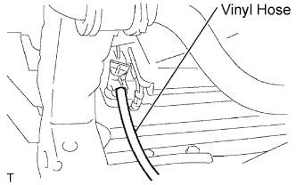
Install a vinyl hose onto the radiator side.
CYLINDER HEAD > REMOVAL |
| 1. REMOVE HOOD SUB-ASSEMBLY |
| 2. DISCHARGE FUEL SYSTEM PRESSURE |
| 3. REMOVE NO. 1 ENGINE UNDER COVER SUB-ASSEMBLY (for Pre Runner and 4WD Type) |
Remove the 4 bolts, then remove the No. 1 engine under cover.
| 4. REMOVE NO. 2 ENGINE UNDER COVER SUB-ASSEMBLY (for Pre Runner and 4WD Type, Regular Cab) |
Remove the 4 bolts, then remove the No. 2 engine under cover.
| 5. DRAIN ENGINE OIL |
Remove the oil filler cap.
Remove the oil pan drain plug and drain the engine oil.
Install a new gasket, then install the oil pan drain plug.
| 6. DRAIN ENGINE COOLANT |
Remove the 4 bolts, then remove the engine under cover No. 1. (PRE RUNNER AND 4WD TYPE)
|
Install a vinyl hose onto the radiator side.
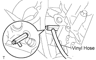 |
Install a vinyl hose onto the engine side.
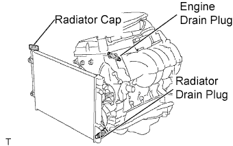 |
Loosen the engine drain plug.
Loosen the radiator drain plug.
Remove the radiator cap and drain coolant.
Drain the coolant from the reservoir tank.
| 7. REMOVE BATTERY |
| 8. REMOVE BATTERY TRAY |
| 9. REMOVE RADIATOR SUPPORT TO FRAME SEAL LH |
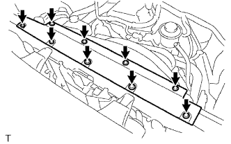 |
Disengage the 9 clips, then remove the radiator support to frame seal LH.
| 10. REMOVE FAN SHROUD |
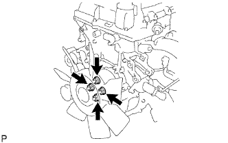 |
Loosen the 4 nuts shown in the illustration.
Remove the fan and generator V belt.
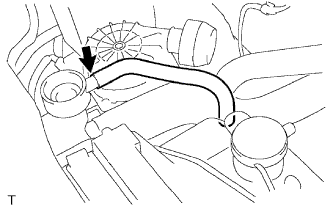 |
Disconnect the radiator reserve tank hose from the radiator.
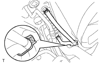 |
Disconnect the oil cooler inlet and outlet hoses from the fan shroud. (for Automatic Transmission)
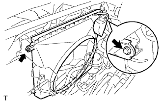 |
Remove the 2 bolts shown in the illustration.
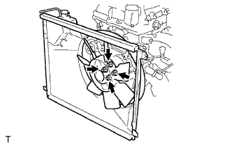 |
Remove the 4 nuts, then remove the fan shroud and fan with fluid coupling together.
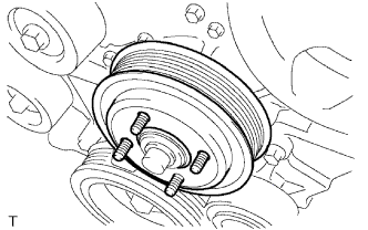 |
Remove the fan pulley.
| 11. REMOVE AIR CLEANER CAP SUB-ASSEMBLY |
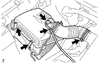 |
Disconnect the mass air flow meter connector.
Disconnect the wire harness clamp.
Loosen the hose clamp bolt, then disconnect the air cleaner hose No. 1.
Disconnect the 2 air cleaner clamps.
Remove the air cleaner cap together with the air cleaner hose No. 1.
| 12. REMOVE AIR CLEANER FILTER ELEMENT SUB-ASSEMBLY |
| 13. REMOVE AIR CLEANER CASE |
Remove the 3 bolts, then remove the air cleaner case.
| 14. SEPARATE VANE PUMP ASSEMBLY |
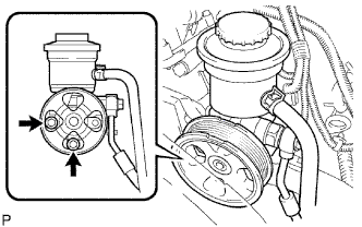 |
Disconnect the vane pump connector.
Remove the 2 bolts, then separate the vane pump.
| 15. REMOVE NO. 2 RADIATOR HOSE |
| 16. SEPARATE COMPRESSOR AND MAGNETIC CLUTCH (w/ Air Conditioning) |
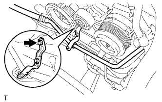 |
Remove the bolt shown in the illustration.
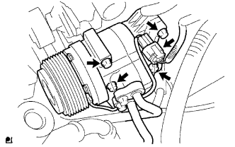 |
Disconnect the compressor and magnetic clutch connector.
Remove the 4 bolts, then separate the compressor and magnetic clutch.
| 17. REMOVE RADIATOR HOSE INLET |
| 18. SEPARATE WATER HOSE SUB-ASSEMBLY |
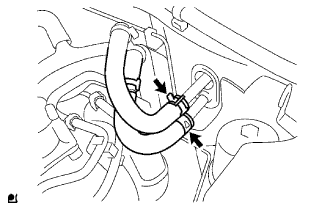 |
Separate the water hoses.
| 19. DISCONNECT FUEL HOSE |
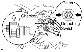 |
Pull the checker of the fuel hose upward.
Pinch the detaching switch of the fuel hose connector and pull out the fuel hose.
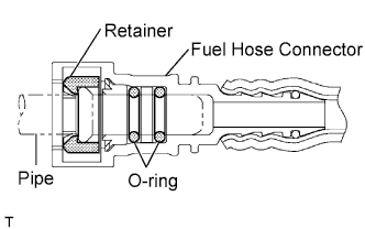 |
| 20. DISCONNECT NO. 2 FUEL HOSE |
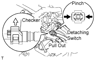 |
Pull the checker of the fuel hose upward.
Pinch the detaching switch of the fuel hose connector and pull out the fuel hose.
|
| 21. SEPARATE FUEL VAPOR FEED HOSE ASSEMBLY |
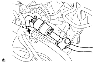 |
Disconnect the fuel vapor feed hose.
| 22. DISCONNECT NO. 1 AIR INJECTION HOSE |
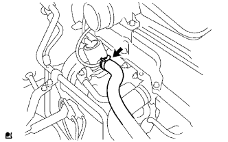 |
Disconnect the No.1 air injection hose.
| 23. DISCONNECT ENGINE WIRE |
Disconnect the connector from the ECM, then pull the engine wire harness to the compartment side.
Disconnect all wire harnesses and connectors in the engine room.
| 24. REMOVE EXHAUST PIPE ASSEMBLY TAIL |
Remove the 2 bolts and 2 nuts.
Remove the exhaust pipe tail from the 4 exhaust pipe supports.
Remove the gasket from the exhaust pipe front.
| 25. REMOVE EXHAUST PIPE ASSEMBLY FRONT |
Remove the 2 bolts and 2 compression springs.
Remove the exhaust pipe front from the exhaust pipe support.
Remove the gasket from the exhaust manifold.
| 26. REMOVE MANUAL TRANSMISSION UNIT ASSEMBLY (for Manual Transmission) |
| Transmission | See page |
| R155 |
Click here
|
| R155F |
Click here
|
| 27. REMOVE AUTOMATIC TRANSMISSION ASSEMBLY (for Automatic Transmission) |
| Transmission | See page |
| A340E |
Click here
|
| A340F |
Click here
|
| 28. REMOVE ENGINE ASSEMBLY |
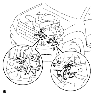 |
Attach the engine sling device and chain block to the engine hangers.
Keep the engine level, and align the engine mounting bracket front No. 1 RH w/ engine mounting insulator front and LH with the body mountings.
Attach the engine mounting bracket front No. 1 RH w/ engine mounting insulator front and LH, and install the 4 bolts and nuts.
Remove the bolts, then remove the engine hangers.
| 29. REMOVE CLUTCH COVER ASSEMBLY (for Manual Transmission) |
| Transmission | See page |
| R155 |
Click here
|
| R155F |
Click here
|
| 30. REMOVE CLUTCH DISC ASSEMBLY (for Manual Transmission) |
| Transmission | See page |
| R155 |
Click here
|
| R155F |
Click here
|
| 31. REMOVE FLYWHEEL SUB-ASSEMBLY (for Automatic Transmission) |
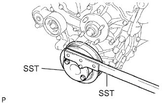 |
Using SST, hold the crankshaft pulley.
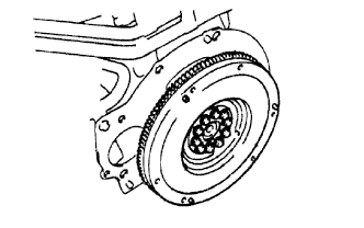 |
Remove the 10 bolts, then remove the flywheel.
| 32. REMOVE DRIVE PLATE AND RING GEAR SUB-ASSEMBLY (for Manual Transmission) |
|
Using SST, hold the crankshaft pulley.
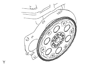 |
Remove the 10 bolts, drive plate spacer rear, drive plate and ring gear and drive plate spacer front.
| 33. REMOVE REAR END PLATE |
Remove the 2 bolts, then remove the rear end plate.
| 34. REMOVE INTAKE AIR CONNECTOR |
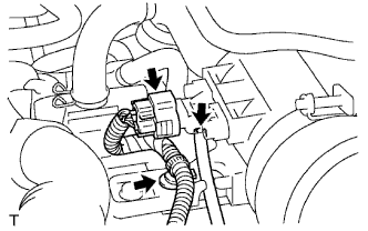 |
Disconnect the pressure sensor connector.
Disengage the wire harness clamp.
Disconnect the vacuum hose.
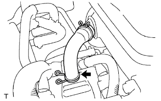 |
Disconnect the No. 2 ventilation hose.
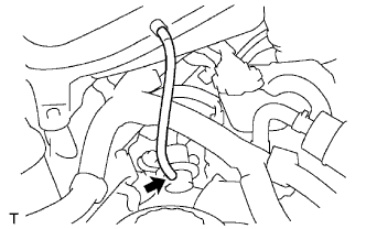 |
Disconnect the vacuum hose.
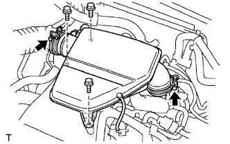 |
Loosen the 2 hose clamp bolts.
Remove the 3 bolts, then remove the intake air connector.
| 35. REMOVE GENERATOR ASSEMBLY |
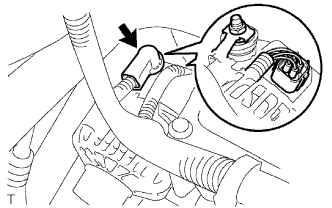 |
Remove the terminal cap.
Remove the nut, then remove the generator wire.
Disconnect the generator connector.
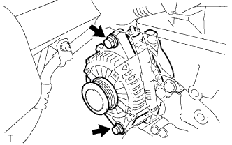 |
Remove the 2 bolts, then remove the generator.
| 36. REMOVE NO. 1 EXHAUST MANIFOLD HEAT INSULATOR |
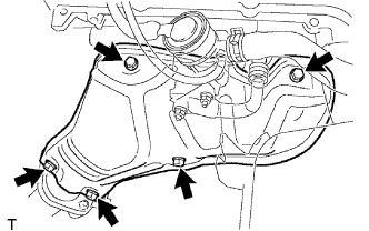 |
Remove the 5 bolts, then remove the exhaust manifold heat insulator No. 1.
| 37. REMOVE INTAKE PIPE INSULATOR |
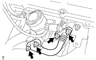 |
Remove the 4 nuts, then remove the intake pipe insulator.
Remove the 2 gaskets.
| 38. REMOVE AIR SWITCHING VALVE ASSEMBLY |
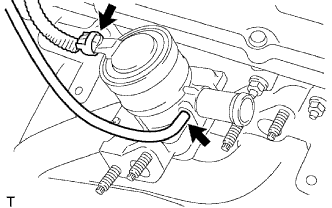 |
Disconnect the vacuum hose.
Disconnect the air switching valve connector.
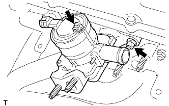 |
Remove the 2 nuts, then remove the air switching valve.
Remove the gasket.
| 39. REMOVE EXHAUST MANIFOLD |
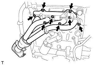 |
Remove the 8 nuts, then remove the exhaust manifold.
| 40. REMOVE V-RIBBED BELT TENSIONER ASSEMBLY |
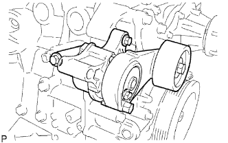 |
Remove the 3 bolts, then remove the V-ribbed belt tensioner.
| 41. REMOVE NO. 1 IDLER PULLEY SUB-ASSEMBLY |
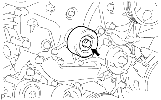 |
Remove the bolt and No. 1 idler pulley sub-assembly.
| 42. REMOVE IDLE PULLEY ASSEMBLY WITH BRACKET (w/ Air Conditioning System) |
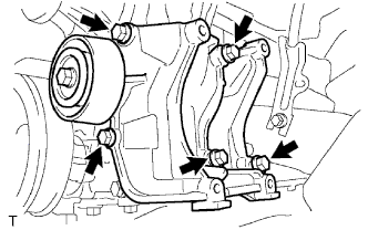 |
Remove the 5 bolts, then remove the idle pulley with bracket.
| 43. REMOVE CRANKSHAFT POSITION SENSOR |
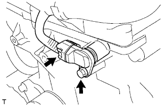 |
Disconnect the camshaft position sensor connector.
Remove the bolt, then remove the camshaft position sensor.
| 44. REMOVE CAMSHAFT POSITION SENSOR |
|
Disconnect the camshaft position sensor connector.
Remove the bolt, then remove the camshaft position sensor.
| 45. REMOVE NO. 1 INTAKE MANIFOLD HEAD GASKET |
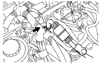 |
Disconnect the fuel vapor feed hose from the VSV.
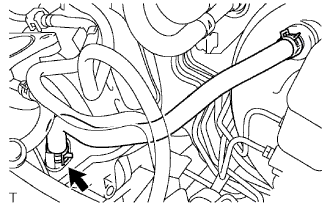 |
Disconnect the vacuum hose.
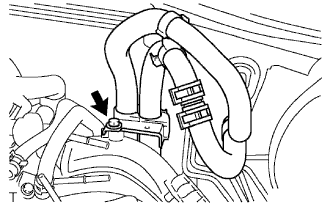 |
Remove the bolt, then remove the clamp bracket.
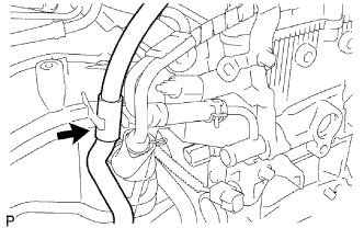 |
Disconnect the water by-pass hose No. 2.
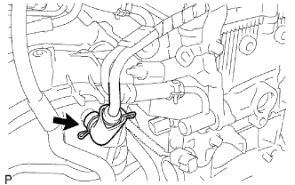 |
Disconnect the ventilation hose No. 3.
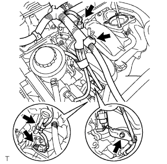 |
Disconnect the VSV connector.
Disengage the engine wire harness clamp.
Disconnect the compressor magnetic clutch connector. (w/ AIR CONDITIONING)
Disengage the wire harness clamp.
Remove the bolt and harness clamp bracket.
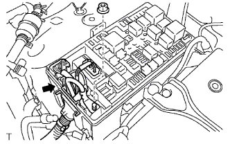 |
Disconnect the 3 connectors.
Remove the nut shown in the illustration.
Disconnect the engine wire harness from the relay block.
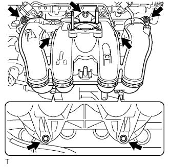 |
Remove the 5 bolts and 2 nuts, then remove the intake manifold.
| 46. REMOVE CYLINDER HEAD COVER SUB-ASSEMBLY |
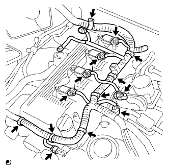 |
Disconnect the ignition coil connectors.
Disconnect the throttle with motor body connector.
Disconnect the VSV connector.
Disconnect the camshaft position sensor connector.
Disconnect the engine wire harness clamps.
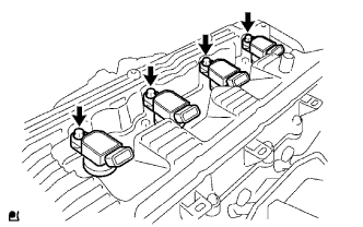 |
Remove the bolts, then remove the ignition coils.
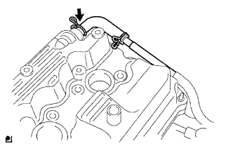 |
Disconnect the ventilation hose.
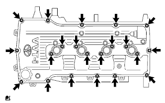 |
Remove the 19 bolts and 2 nuts, then remove the cylinder head cover.
| 47. REMOVE CRANKSHAFT PULLEY |
|
Remove the bolt, then separate the bracket. (w/ AIR CONDITIONING)
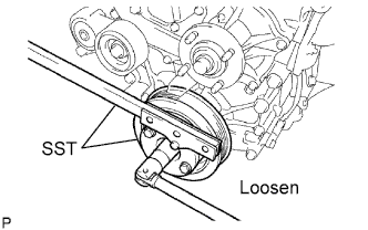 |
Using SST, loosen the crankshaft pulley bolt.
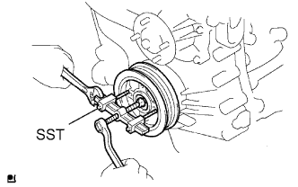 |
Using SST, remove the crankshaft pulley and crankshaft pulley bolt.
| 48. REMOVE OIL LEVEL GAGE SUB-ASSEMBLY |
| 49. REMOVE NO. 2 OIL PAN SUB-ASSEMBLY |
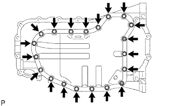 |
Remove the 18 bolts and 2 nuts.
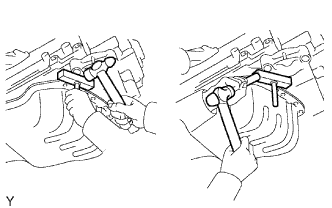 |
Insert the blade of oil pan seal cutter between the pans. Cut through the applied sealer and remove the oil pan.
| 50. REMOVE OIL STRAINER SUB-ASSEMBLY |
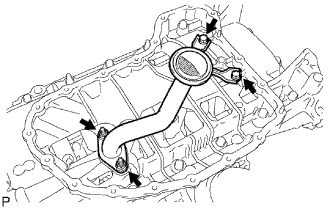 |
Remove the 2 bolts, 2 nuts, oil strainer and gasket.
| 51. REMOVE OIL PAN SUB-ASSEMBLY |
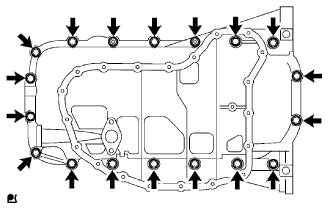 |
Remove the 16 bolts and 2 nuts.
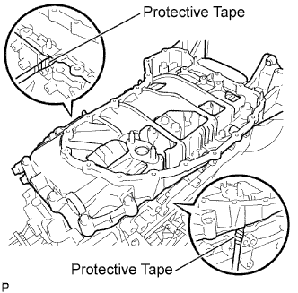 |
Remove the oil pan by prying between the oil pan and cylinder block with a screwdriver.
| 52. REMOVE TIMING CHAIN COVER |
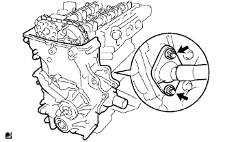 |
Remove the 2 nuts, then separate the water by-pass pipe No. 1.
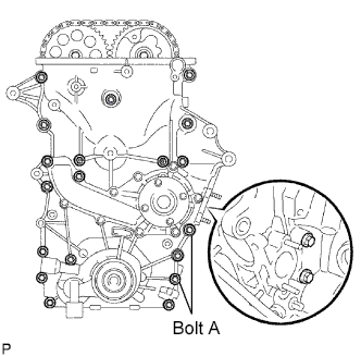 |
Remove the 19 bolts and 2 nuts shown in the illustration.
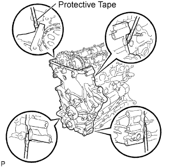 |
Remove the oil pump by prying between the oil pump and cylinder head or cylinder block with a screwdriver.
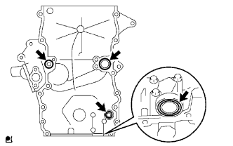 |
Remove the 4 O-rings.
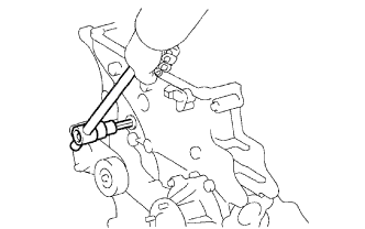 |
Using a 10 mm socket hexagon wrench, remove the head straight screw plug.
| 53. REMOVE TIMING CHAIN GUIDE |
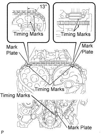 |
Make sure that each matchmark is in the position shown in the illustration.
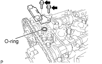 |
Remove the 2 bolts, timing chain guide and O-ring.
| 54. REMOVE NO. 1 CHAIN TENSIONER ASSEMBLY |
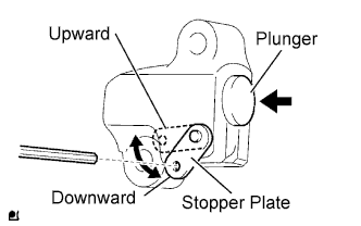 |
Move the stopper plate upward to release the lock, and push the plunger deep into the tensioner.
Move the stopper plate downward to set the lock, and insert a 3.0 mm (0.118 in.) diameter bar into the stopper plate hole.
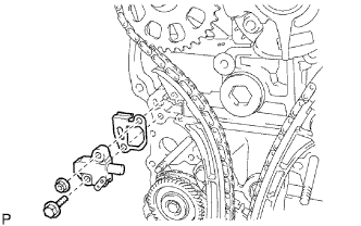 |
Remove the bolt, nut, chain tensioner and gasket.
| 55. REMOVE CHAIN TENSIONER SLIPPER |
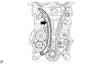 |
Remove the bolt and tensioner slipper.
| 56. REMOVE NO. 1 CHAIN VIBRATION DAMPER |
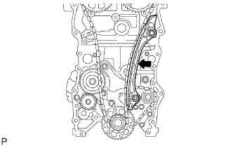 |
Remove the 2 bolts and vibration damper.
| 57. REMOVE CHAIN SUB-ASSEMBLY |
| 58. REMOVE CAMSHAFT |
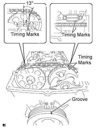 |
Set the No. 1 cylinder to the TDC/compression.
Turn the crankshaft pulley clockwise and align its timing mark notch with the timing mark "0".
Check that the timing marks of the camshaft timing gear are located as illustrated.
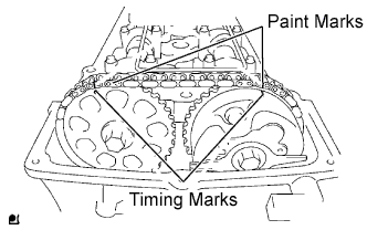 |
Place paint marks on the timing chain plates that align with timing marks of the camshaft timing gear.
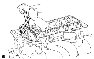 |
Hold the hexagonal lobe of the No. 2 camshaft with an adjustable wrench.
Loosen the bolt.
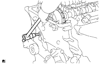 |
Using 10 mm socket hexagon wrench, remove the head straight screw plug.
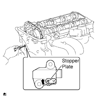 |
Insert a screwdriver into the service hole of the chain tensioner to hold the stopper plate of the chain tensioner lifted up.
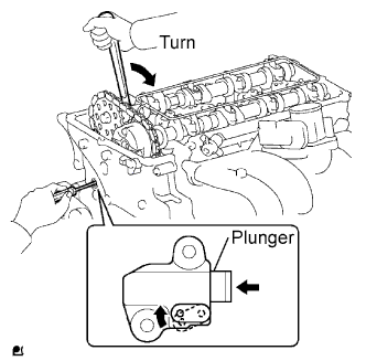 |
While keeping the stopper plate of the chain tensioner lifted up, slightly rotate the hexagonal lobe of the No. 2 camshaft clockwise with an adjustable wrench so the plunger of the chain tensioner is pushed.
Keeping the adjustable wrench installed, remove the screwdriver with the plunger pushed in.
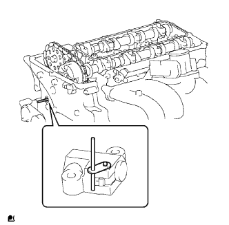 |
Insert a 3.0 mm (0.118 in.) diameter bar into the hole of the stopper plate with the stopper plate of the chain tensioner lifted down and locked.
Secure the 3.0 mm (0.118 in.) diameter bar with tape.
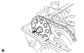 |
Remove the bolt, then remove the camshaft timing gear.
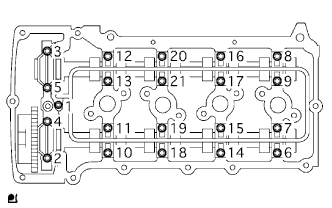 |
Using several steps, uniformly loosen and remove the 21 bearing cap bolts in the sequence shown in the illustration.
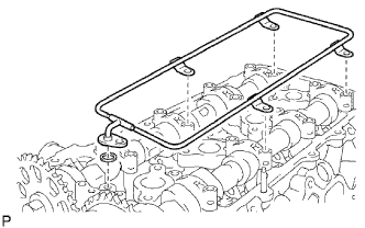 |
Remove the camshaft oil delivery pipe and O-ring.
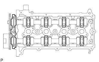 |
Remove the camshaft bearing cap No. 1 and 8 camshaft bearing caps No. 2.
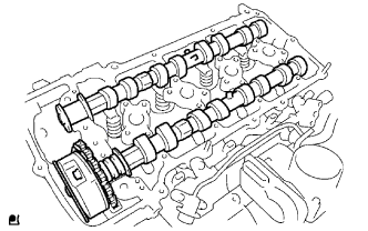 |
Remove the camshaft and No. 2 camshaft.
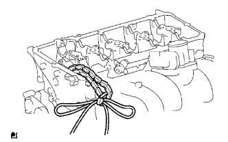 |
Tie the chain with a piece of string or wire.
| 59. REMOVE NO. 1 VALVE ROCKER ARM SUB-ASSEMBLY |
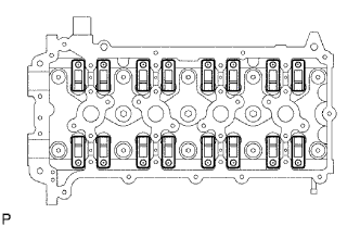 |
Remove the 16 valve rocker arms.
| 60. REMOVE VALVE LASH ADJUSTER ASSEMBLY |
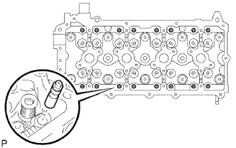 |
Remove the valve lash adjuster.
| 61. REMOVE CYLINDER HEAD SUB-ASSEMBLY |
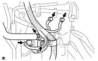 |
Disconnect the water hose shown in the illustration.
Disconnect the engine coolant temperature sensor connector.
Remove the bolts, then separate the wire harnesses.
Remove the bolt, then separate the wire harness bracket.
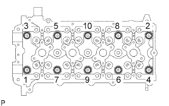 |
Uniformly loosen the 10 bolts in the sequence shown in the illustration. Remove the 10 cylinder head bolts and plate washers.
| 62. REMOVE CYLINDER HEAD GASKET |