 |
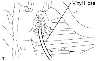
Install a vinyl hose onto the radiator side.
TIMING CHAIN > REMOVAL |
| 1. REMOVE HOOD SUB-ASSEMBLY |
| 2. DISCHARGE FUEL SYSTEM PRESSURE |
| 3. REMOVE NO. 1 ENGINE UNDER COVER SUB-ASSEMBLY (for 4WD and Pre-Runner) |
Remove the 4 bolts, then remove the No. 1 engine under cover.
| 4. REMOVE NO. 2 ENGINE UNDER COVER SUB-ASSEMBLY (for 4WD and Pre-Runner, Regular Cab) |
Remove the 4 bolts, then remove the No. 2 engine under cover.
| 5. DRAIN ENGINE OIL |
Remove the oil filler cap.
Remove the oil pan drain plug and drain the engine oil.
Install a new gasket, then install the oil pan drain plug.
| 6. DRAIN ENGINE COOLANT |
Remove the 4 bolts, then remove the engine under cover No. 1. (PRE RUNNER AND 4WD TYPE)
|
Install a vinyl hose onto the radiator side.
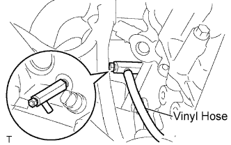 |
Install a vinyl hose onto the engine side.
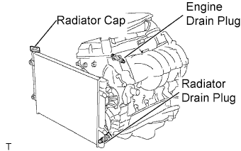 |
Loosen the engine drain plug.
Loosen the radiator drain plug.
Remove the radiator cap and drain coolant.
Drain the coolant from the reservoir tank.
| 7. REMOVE BATTERY |
| 8. REMOVE BATTERY TRAY |
| 9. REMOVE RADIATOR SUPPORT TO FRAME SEAL LH |
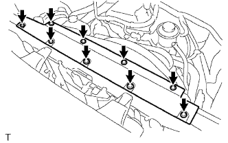 |
Disengage the 9 clips, then remove the radiator support to frame seal LH.
| 10. REMOVE FAN SHROUD |
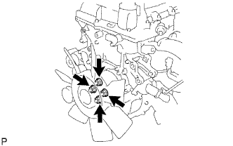 |
Loosen the 4 nuts shown in the illustration.
Remove the fan and generator V belt.
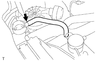 |
Disconnect the radiator reserve tank hose from the radiator.
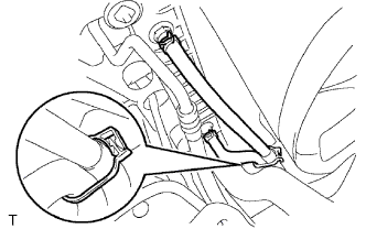 |
Disconnect the oil cooler inlet and outlet hoses from the fan shroud. (for Automatic Transmission)
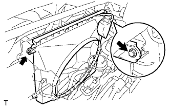 |
Remove the 2 bolts shown in the illustration.
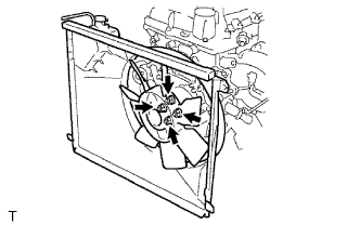 |
Remove the 4 nuts, then remove the fan shroud and fan with fluid coupling together.
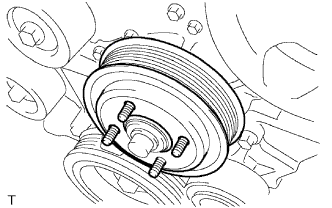 |
Remove the fan pulley.
| 11. REMOVE AIR CLEANER CAP SUB-ASSEMBLY |
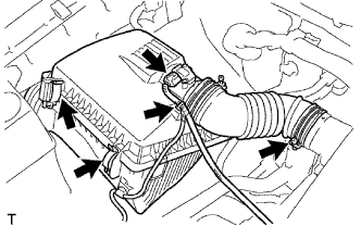 |
Disconnect the mass air flow meter connector.
Disconnect the wire harness clamp.
Loosen the hose clamp bolt, then disconnect the air cleaner hose No. 1.
Disconnect the 2 air cleaner clamps.
Remove the air cleaner cap together with the air cleaner hose No. 1.
| 12. REMOVE AIR CLEANER FILTER ELEMENT SUB-ASSEMBLY |
| 13. REMOVE AIR CLEANER CASE |
Remove the 3 bolts, then remove the air cleaner case.
| 14. SEPARATE VANE PUMP ASSEMBLY |
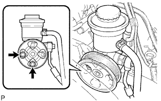 |
Disconnect the vane pump connector.
Remove the 2 bolts, then separate the vane pump.
| 15. REMOVE NO. 2 RADIATOR HOSE |
| 16. SEPARATE COMPRESSOR AND MAGNETIC CLUTCH (w/ Air Conditioning System) |
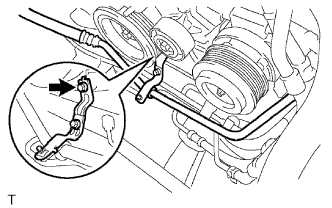 |
Remove the bolt shown in the illustration.
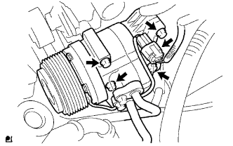 |
Disconnect the compressor and magnetic clutch connector.
Remove the 4 bolts, then separate the compressor and magnetic clutch.
| 17. REMOVE RADIATOR HOSE INLET |
| 18. SEPARATE WATER HOSE SUB-ASSEMBLY |
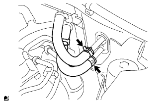 |
Separate the water hoses.
| 19. DISCONNECT FUEL HOSE |
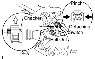 |
Pull the checker of the fuel hose upward.
Pinch the detaching switch of the fuel hose connector and pull out the fuel hose.
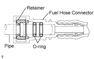 |
| 20. DISCONNECT FUEL HOSE NO.2 |
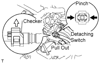 |
Pull the checker of the fuel hose upward.
Pinch the detaching switch of the fuel hose connector and pull out the fuel hose.
|
| 21. SEPARATE FUEL VAPOR FEED HOSE ASSEMBLY |
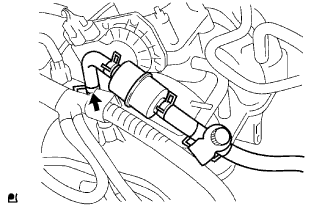 |
Disconnect the fuel vapor feed hose.
| 22. DISCONNECT NO. 1 AIR INJECTION HOSE |
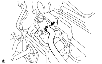 |
Disconnect the No.1 air injection hose.
| 23. DISCONNECT ENGINE WIRE |
Disconnect the connector from the ECM, then pull the engine wire harness to the compartment side.
Disconnect all wire harnesses and connectors in the engine room.
| 24. REMOVE EXHAUST PIPE ASSEMBLY |
Remove the 2 bolts and 2 nuts.
Remove the exhaust pipe tail from the 4 exhaust pipe supports.
Remove the gasket from the exhaust pipe front.
| 25. REMOVE FRONT EXHAUST PIPE ASSEMBLY |
Remove the 2 bolts and 2 compression springs.
Remove the exhaust pipe front from the exhaust pipe support.
Remove the gasket from the exhaust manifold.
| 26. REMOVE MANUAL TRANSMISSION UNIT ASSEMBLY (for Manual Transmission) |
| Transmission | See page |
| R155 |
Click here
|
| R155F |
Click here
|
| 27. REMOVE AUTOMATIC TRANSMISSION ASSEMBLY (for Automatic Transmission) |
| Transmission | See page |
| A340E |
Click here
|
| A340F |
Click here
|
| 28. REMOVE ENGINE ASSEMBLY |
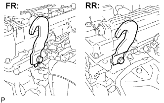 |
Install the engine hanger with the bolt.
| Part Name | Part No. |
| Engine hanger | 12281-75040 |
| Bolt | 91552-A1020 |
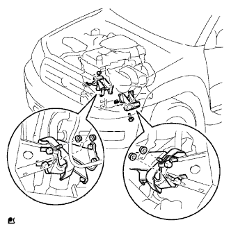 |
Attach the engine sling device and chain block to the engine hangers.
Remove the 4 bolts and 4 nuts.
Lift the engine out of the vehicle slowly and carefully by operating the engine sling device and chain block.
| 29. REMOVE CLUTCH COVER ASSEMBLY (for Manual Transmission) |
| Transmission | See page |
| R155 |
Click here
|
| R155F |
Click here
|
| 30. REMOVE CLUTCH DISC ASSEMBLY (for Manual Transmission) |
| Transmission | See page |
| R155 |
Click here
|
| R155F |
Click here
|
| 31. REMOVE FLYWHEEL SUB-ASSEMBLY (for Manual Transmission) |
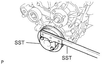 |
Using SST, hold the crankshaft pulley.
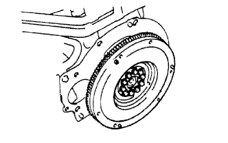 |
Remove the 10 bolts, then remove the flywheel.
| 32. REMOVE DRIVE PLATE AND RING GEAR SUB-ASSEMBLY (for Automatic Transmission) |
|
Using SST, hold the crankshaft pulley.
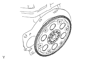 |
Remove the 10 bolts, drive plate spacer rear, drive plate and ring gear and drive plate spacer front.
| 33. REMOVE REAR END PLATE |
Remove the 2 bolts, then remove the rear end plate.
| 34. REMOVE INTAKE AIR CONNECTOR |
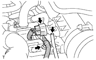 |
Disconnect the pressure sensor connector.
Disengage the wire harness clamp.
Disconnect the vacuum hose.
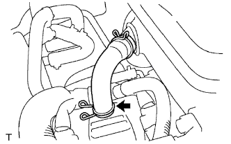 |
Disconnect the No. 2 ventilation hose.
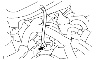 |
Disconnect the vacuum hose.
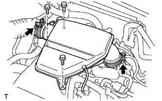 |
Loosen the 2 hose clamp bolts.
Remove the 3 bolts, then remove the intake air connector.
| 35. REMOVE GENERATOR ASSEMBLY |
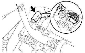 |
Remove the terminal cap.
Remove the nut, then remove the generator wire.
Disconnect the generator connector.
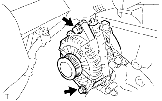 |
Remove the 2 bolts, then remove the generator.
| 36. REMOVE V-RIBBED BELT TENSIONER ASSEMBLY |
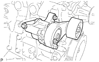 |
Remove the 3 bolts, then remove the V-ribbed belt tensioner.
| 37. REMOVE NO. 1 IDLER PULLEY SUB-ASSEMBLY |
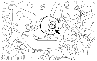 |
Remove the bolt and No. 1 idler pulley sub-assembly.
| 38. REMOVE IDLE PULLEY ASSEMBLY WITH BRACKET (w/ Air Conditioning System) |
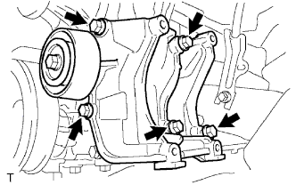 |
Remove the 5 bolts, then remove the idle pulley with bracket.
| 39. REMOVE CRANKSHAFT POSITION SENSOR |
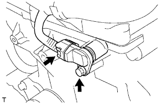 |
Disconnect the camshaft position sensor connector.
Remove the bolt, then remove the camshaft position sensor.
| 40. REMOVE CAMSHAFT POSITION SENSOR |
|
Disconnect the camshaft position sensor connector.
Remove the bolt, then remove the camshaft position sensor.
| 41. REMOVE NO. 1 INTAKE MANIFOLD TO HEAD GASKET |
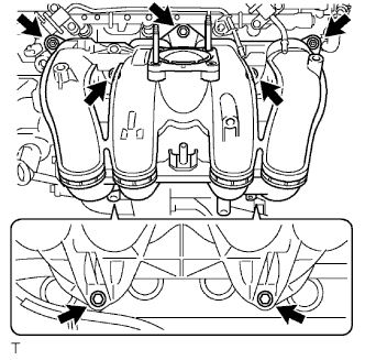 |
Install a new gasket onto the intake manifold.
Install the intake manifold with the 5 bolts and 2 nuts.
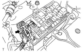 |
Connect the engine wire harness to the relay block.
Install the nut shown in the illustration.
Connect the 3 connectors.
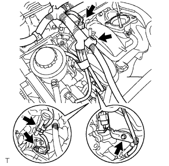 |
Install the harness clamp bracket with the bolt.
Engage the wire harness clamp.
Connect the compressor magnetic clutch connector. (w/ AIR CONDITIONING)
Engage the engine wire harness clamp.
Connect the VSV connector.
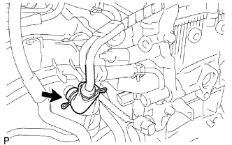 |
Connect the ventilation hose No. 3.
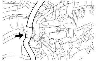 |
Connect the water by-pass hose No. 2.
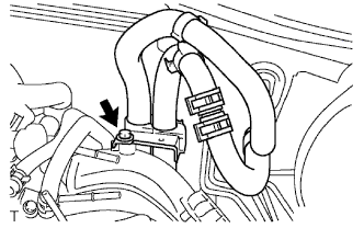 |
Install the clamp bracket with the bolt.
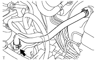 |
Connect the vacuum hose.
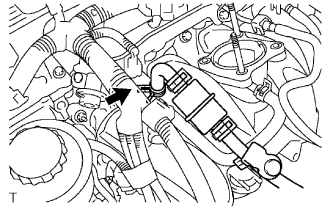 |
Connect the fuel vapor feed hose to the VSV.
| 42. REMOVE CYLINDER HEAD COVER SUB-ASSEMBLY |
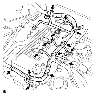 |
Disconnect the ignition coil connectors.
Disconnect the throttle with motor body connector.
Disconnect the VSV connector.
Disconnect the camshaft position sensor connector.
Disconnect the engine wire harness clamps.
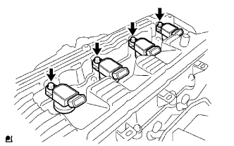 |
Remove the bolts, then remove the ignition coils.
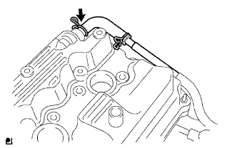 |
Disconnect the ventilation hose.
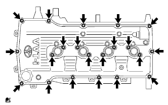 |
Remove the 19 bolts and 2 nuts, then remove the cylinder head cover.
| 43. REMOVE CRANKSHAFT PULLEY |
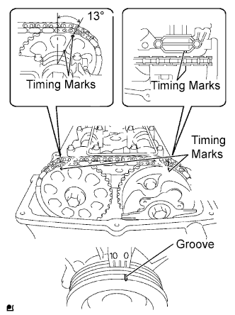 |
Set the No. 1 cylinder to the TDC/ compression.
Turn the crankshaft pulley clockwise and align its timing mark notch with the timing mark "0".
Check that the timing marks of the camshaft timing gear are located as illustrated.
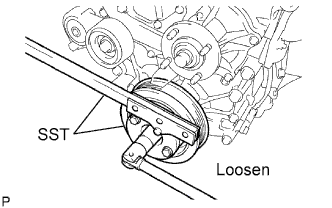 |
Using SST, loosen the crankshaft pulley bolt.
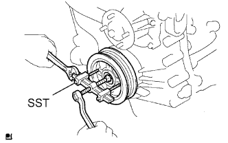 |
Using SST, remove the crankshaft pulley and crankshaft pulley bolt.
| 44. REMOVE OIL LEVEL GAGE SUB-ASSEMBLY |
| 45. REMOVE NO. 2 OIL PAN SUB-ASSEMBLY |
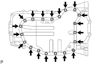 |
Remove the 18 bolts and 2 nuts.
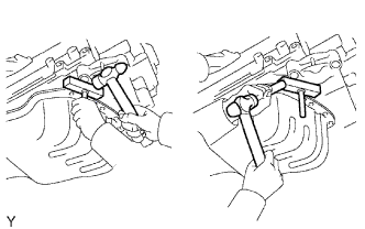 |
Insert the blade of oil pan seal cutter between the pans. Cut through the applied sealer and remove the oil pan.
| 46. REMOVE OIL STRAINER SUB-ASSEMBLY |
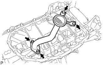 |
Remove the 2 bolts, 2 nuts, oil strainer and gasket.
| 47. REMOVE OIL PAN SUB-ASSEMBLY |
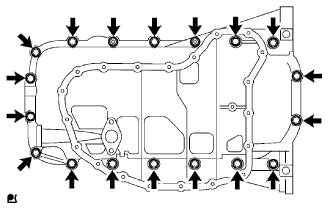 |
Remove the 16 bolts and 2 nuts.
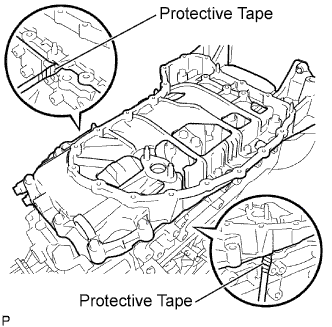 |
Remove the oil pan by prying between the oil pan and cylinder block with a screwdriver.
| 48. REMOVE TIMING CHAIN COVER |
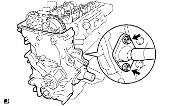 |
Remove the 2 nuts, then separate the water by-pass pipe No. 1.
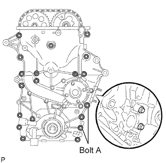 |
Remove the 19 bolts and 2 nuts shown in the illustration.
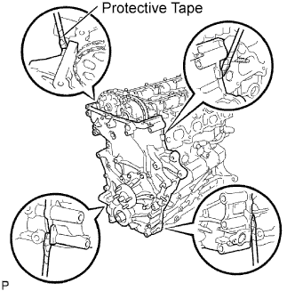 |
Remove the oil pump by prying between the oil pump and cylinder head or cylinder block with a screwdriver.
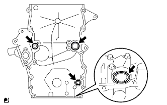 |
Remove the 4 O-rings.
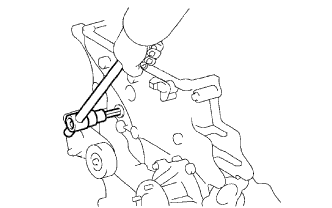 |
Using a 10 mm socket hexagon wrench, remove the head straight screw plug.
| 49. REMOVE TIMING CHAIN GUIDE |
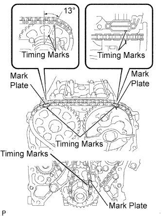 |
Make sure that each matchmark is in the position shown in the illustration.
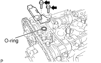 |
Remove the 2 bolts, timing chain guide and O-ring.
| 50. REMOVE NO. 1 CHAIN TENSIONER ASSEMBLY |
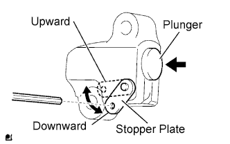 |
Move the stopper plate upward to release the lock, and push the plunger deep into the tensioner.
Move the stopper plate downward to set the lock, and insert a 3.0 mm (0.118 in.) diameter bar into the stopper plate hole.
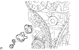 |
Remove the bolt, nut, chain tensioner and gasket.
| 51. REMOVE CHAIN TENSIONER SLIPPER |
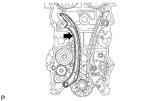 |
Remove the bolt and tensioner slipper.
| 52. REMOVE NO. 1 CHAIN VIBRATION DAMPER |
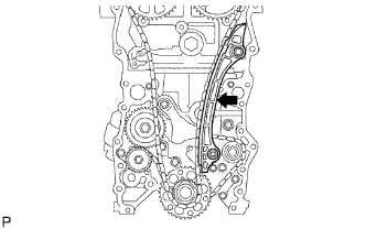 |
Remove the 2 bolts and vibration damper.
| 53. REMOVE CHAIN SUB-ASSEMBLY |
| 54. REMOVE CRANKSHAFT TIMING GEAR OR SPROCKET |
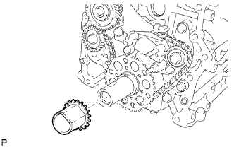 |
Remove the crankshaft timing gear from the crankshaft.
| 55. REMOVE NO. 2 CHAIN VIBRATION DAMPER |
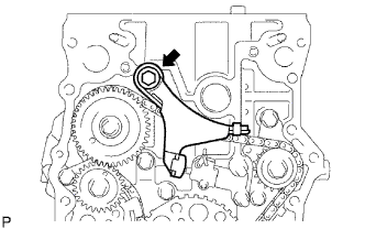 |
Remove the bolt and No. 2chain vibration damper.
| 56. REMOVE NO. 3 CHAIN VIBRATION DAMPER |
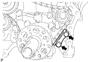 |
Remove the 2 bolts and No. 3chain vibration damper.
| 57. REMOVE NO. 2 CHAIN TENSIONER ASSEMBLY |
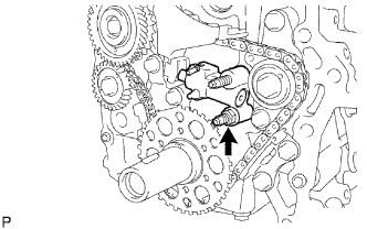 |
Remove the nut and No. 2 chain tensioner assembly.
| 58. REMOVE NO.2 CHAIN SUB-ASSEMBLY |
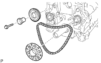 |
Remove the bolt, balanceshaft drive gear shaft and balanceshaft drive gear.
Remove the crankshaft timing sprocket No. 2 and chain.