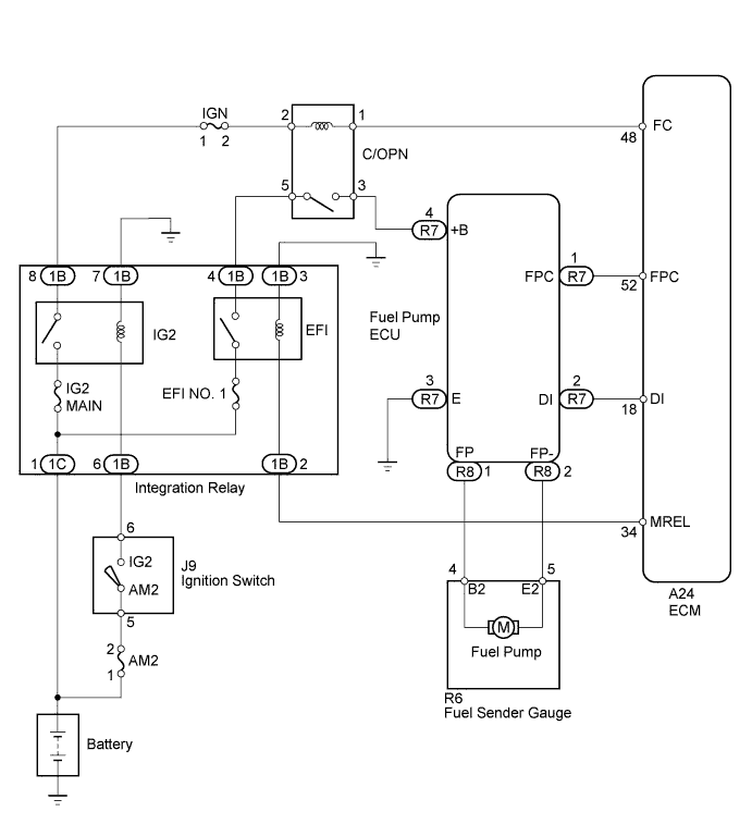
DTC P0230 Fuel Pump Primary Circuit |
| DTC Code | DTC Detection Condition | Trouble Area |
| P0230 | When either condition below is met: (1 trip detection logic)
|
|
| 1.CHECK DTC OUTPUT |
Connect the Techstream to the DLC3.
Turn the ignition switch ON.
Enter the following menus: Body Electrical / Combination Meter / Trouble Codes.
Read the DTC
| Result | Proceed to |
| DTC B1500 is not output | A |
| DTC B1500 is output | B |
|
| ||||
| A | |
 |
| 2.PERFORM ACTIVE TEST USING TECHSTREAM |
Connect the Techstream to the DLC3.
Turn the ignition switch ON and turn the Techstream ON.
Enter the following menus: Powertrain / Engine and ECT / Active Test / Control the fuel pump / Speed.
Check whether operating sounds can be heard while operating the relay using the Techstream.
|
| ||||
| OK | |
|
| 3.CHECK HARNESS AND CONNECTOR (FUEL PUMP ECU - ECM, BODY GROUND) |
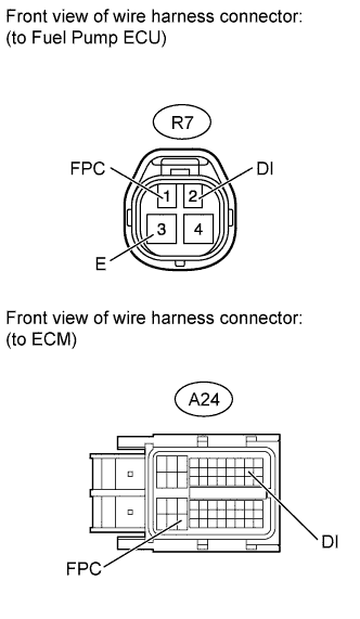 |
Disconnect the R7 fuel pump ECU connector.
Disconnect the A24 ECM connector.
Measure the resistance according to the value(s) in the table below.
| Tester Connection | Condition | Specified Condition |
| R7-1 (FPC) - A24-52 (FPC) | Always | Below 1 Ω |
| R7-2 (DI) - A24-18 (DI) | Always | Below 1 Ω |
| R7-3 (E) - Body ground | Always | Below 1 Ω |
| Tester Connection | Condition | Specified Condition |
| R7-1 (FPC) or A24-52 (FPC) - Body ground | Always | 10 kΩ or higher |
| R7-2 (DI) or A24-18 (DI) - Body ground | Always | 10 kΩ or higher |
|
| ||||
| OK | |
|
| 4.REPLACE FUEL PUMP ECU |
Replace the fuel pump ECU (Click here).
| NEXT | |
|
| 5.CONFIRM WHETHER DTC OUTPUT RECURS |
Check that there is 17 L or more of fuel remaining.
Connect the Techstream to the DLC3.
Turn the ignition switch ON.
Turn the Techstream ON.
Clear DTCs (Click here).
Start the engine and idle it for 5 minutes.
Drive the vehicle in an urban area for approximately 10 minutes.
Enter the following menus: Powertrain / Engine and ECT / Trouble Codes.
Read the DTCs.
| Display (DTC Output) | Proceed to |
| No output | A |
| Other DTCs | B |
|
| ||||
| A | ||
 | ||
| ||
| 6.INSPECT CIRCUIT OPENING RELAY (C/OPN) |
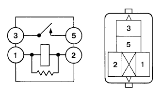 |
Remove the circuit opening relay (C/OPN) from the engine room relay block .
Measure the resistance according to the value(s) in the table below.
| Standard resistance | Condition | Specified Condition |
| 3 - 5 | When no battery voltage applied to terminals 1 and 2 | 10 kΩ or higher |
| 3 - 5 | When battery voltage applied to terminals 1 and 2 | Below 1 Ω |
|
| ||||
| OK | |
|
| 7.INSPECT CIRCUIT OPENING RELAY (C/OPN) (POWER SOURCE VOLTAGE) |
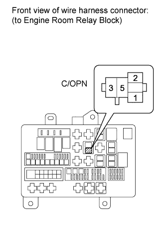 |
Remove the circuit opening relay (C/OPN) from the engine room relay block .
Turn the ignition switch ON.
Measure the voltage according to the value(s) in the table below.
| Tester Connection | Switch Condition | Specified Condition |
| C/OPN relay (2) - Body ground | Ignition switch ON | 11 to 14 V |
| C/OPN relay (5) - Body ground | Ignition switch ON | 11 to 14 V |
|
| ||||
| OK | |
|
| 8.CHECK HARNESS AND CONNECTOR (C/OPN RELAY - ECM, FUEL PUMP ECU) |
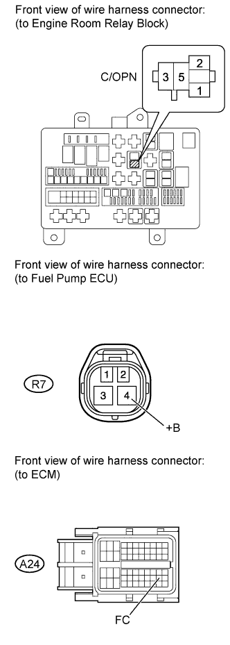 |
Remove the circuit opening relay (C/OPN) from the engine room relay block .
Disconnect the R7 fuel pump ECU connector.
Disconnect the A24 ECM connector.
Measure the resistance according to the value(s) in the table below.
| Tester Connection | Condition | Specified Condition |
| C/OPN relay (1) - A24-48 (FC) | Always | Below 1 Ω |
| C/OPN relay (3) - R7-4 (+B) | Always | Below 1 Ω |
| Tester Connection | Condition | Specified Condition |
| C/OPN relay (1) or A24-48 (FC) - Body ground | Always | 10 kΩ or higher |
| C/OPN relay (3) or R7-4 (+B) - Body ground | Always | 10 kΩ or higher |
|
| ||||
| OK | |
|
| 9.CHECK HARNESS AND CONNECTOR (FUEL PUMP - FUEL PUMP ECU) |
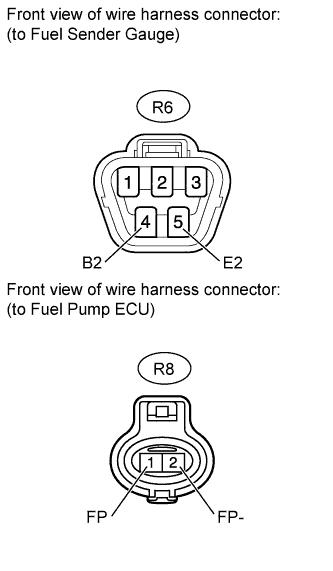 |
Disconnect the R6 fuel pump connector.
Disconnect the R8 fuel pump ECU connector.
Measure the resistance according to the value(s) in the table below.
| Tester Connection | Condition | Specified Condition |
| R6-4 (B2) - R8-1 (FP) | Always | Below 1 Ω |
| R6-5 (E2) - R8-2 (FP-) | Always | Below 1 Ω |
| Tester Connection | Condition | Specified Condition |
| R6-4 (B2) or R8-1 (FP) - Body ground | Always | 10 kΩ or higher |
| R6-5 (E2) or R8-2 (FP-) - Body ground | Always | 10 kΩ or higher |
|
| ||||
| OK | |
|
| 10.INSPECT FUEL PUMP |
Inspect the fuel pump (Click here).
|
| ||||
| OK | |
|
| 11.CHECK HARNESS AND CONNECTOR (FUEL PUMP ECU - ECM, BODY GROUND) |
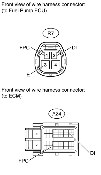 |
Disconnect the R7 fuel pump ECU connector.
Disconnect the A24 ECM connector.
Measure the resistance according to the value(s) in the table below.
| Tester Connection | Condition | Specified Condition |
| R7-1 (FPC) - A24-52 (FPC) | Always | Below 1 Ω |
| R7-2 (DI) - A24-18 (DI) | Always | Below 1 Ω |
| R7-3 (E) - Body ground | Always | Below 1 Ω |
| Tester Connection | Condition | Specified Condition |
| R7-1 (FPC) or A24-52 (FPC) - Body ground | Always | 10 kΩ or higher |
| R7-2 (DI) or A24-18 (DI) - Body ground | Always | 10 kΩ or higher |
|
| ||||
| OK | |
|
| 12.REPLACE FUEL PUMP ECU |
Replace the fuel pump ECU (Click here).
| NEXT | |
|
| 13.CONFIRM WHETHER DTC OUTPUT RECURS |
Connect the Techstream to the DLC3.
Turn the ignition switch ON.
Turn the Techstream ON.
Clear DTCs (Click here).
Start the engine and idle it for 5 minutes.
Drive the vehicle in an urban area for approximately 10 minutes.
Enter the following menus: Powertrain / Engine and ECT/ Trouble Codes.
Read the DTCs.
| Display (DTC Output) | Proceed to |
| No output | A |
| Other DTCs | B |
|
| ||||
| A | ||
| ||
| ||
| 14.CHECK HARNESS AND CONNECTOR (CIRCUIT OPENING RELAY (C/OPN) - IGN FUSE, INTEGRATION RELAY) |
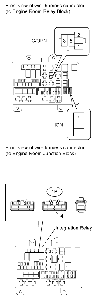 |
Remove the circuit opening relay (C/OPN) from the engine room relay block.
Remove the IGN fuse from the engine room relay block.
Remove the integration relay from the engine room junction block.
Disconnect the 1B integration relay connector.
Measure the resistance according to the value(s) in the table below.
| Tester Connection | Condition | Specified Condition |
| C/OPN relay (2) - IGN fuse (2) | Always | Below 1 Ω |
| C/OPN relay (5) - 1B-4 | Always | Below 1 Ω |
| Tester Connection | Condition | Specified Condition |
| C/OPN relay (2) or IGN fuse (2) - Body ground | Always | 10 kΩ or more |
| C/OPN relay (5) or 1B-4 - Body ground | Always | 10 kΩ or more |
|
| ||||
| OK | ||
| ||
| ||

