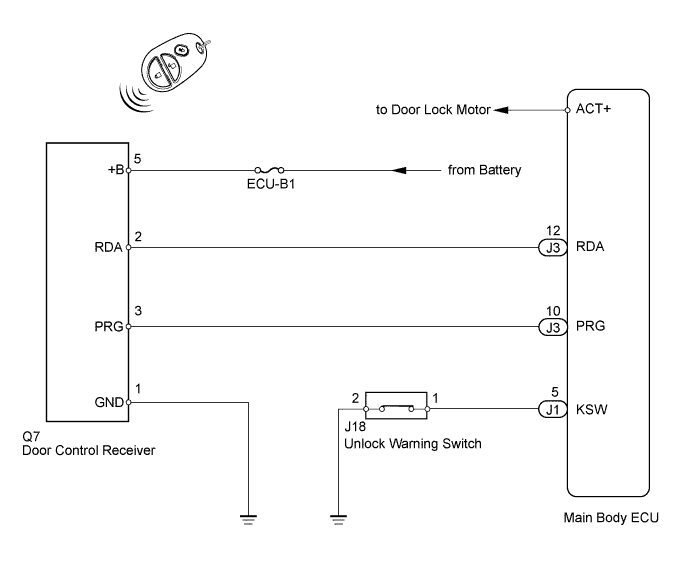
WIRELESS DOOR LOCK CONTROL SYSTEM > Only Wireless Control Function is Inoperative |
| 1.CHECK POWER DOOR LOCK OPERATION FUNCTION |
Check the power door lock operation function (Click here).
|
| ||||
| OK | |
 |
| 2.CHECK KEY REMINDER WARNING OPERATION FUNCTION |
Check the key reminder buzzer operation function (Click here).
|
| ||||
| OK | |
|
| 3.CHECK WIRELESS DOOR CONTROL TRANSMITTER |
Check whether the wireless door lock control functions operate normally with another registered vehicle transmitter.
|
| ||||
| OK | |
|
| 4.CHECK TRANSMITTER BATTERY |
Remove the battery from the inoperative wireless door control transmitter (Click here).
Measure the voltage according to the value(s) in the table below.
| Tester Connection | Condition | Specified Condition |
| Battery positive (+) side - Battery negative (-) side | Always | 2.5 to 3.2 V |
|
| ||||
| OK | ||
 | ||
| ||
| 5.CHECK ELECTRICAL NOISE |
Move the transmitter near the vicinity of the door control receiver.
Press and hold either the LOCK or UNLOCK transmitter switch for 1 second, and check that the doors are locked or unlocked accordingly.
|
| ||||
| OK | ||
| ||
| ||
| 6.CHECK HARNESS AND CONNECTOR (MAIN BODY ECU - DOOR CONTROL RECEIVER) |
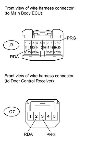 |
Disconnect the J3 ECU connector.
Disconnect the Q7 receiver connector.
Measure the resistance according to the value(s) in the table below.
| Tester Connection | Condition | Specified Condition |
| J3-12 (RDA) - Q7-2 (RDA) | Always | Below 1 Ω |
| J3-10 (PRG) - Q7-3 (PRG) | ||
| J3-12 (RDA) - Q7-2 (RDA) - Body ground | Always | 10 kΩ or higher |
| J3-10 (PRG) - Q7-3 (PRG) - Body ground |
|
| ||||
| OK | |
|
| 7.CHECK HARNESS AND CONNECTOR (DOOR CONTROL RECEIVER - BATTERY AND BODY GROUND) |
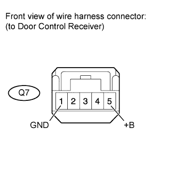 |
Disconnect the Q7 receiver connector.
Measure the resistance and voltage according to the value(s) in the table below.
| Tester Connection | Condition | Specified Condition |
| Q7-5 (+B) - Body Ground | Always | 11 to 14 V |
| Tester Connection | Condition | Specified Condition |
| Q7-1 (GND) - Body ground | Always | Below 1 Ω |
|
| ||||
| OK | |
|
| 8.CHECK DOOR CONTROL RECEIVER (OUTPUT) |
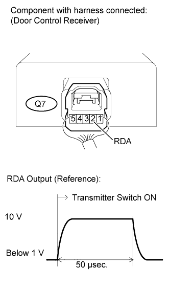 |
Measure the voltage according to the value(s) in the table below.
| Tester Connection | Tool Setting | Switch Condition | Specified Condition |
| Q7-2 (RDA) - Body ground | 10 V/DIV., 50 μsec./DIV. | Transmitter switch ON → OFF (No key in ignition key cylinder, all doors closed) | Pulse generation |
| Result | Proceed to |
| OK | A |
| NG (for Regular Cab) | B |
| NG (for Double Cab) | C |
| NG (for CrewMax) | D |
|
| ||||
|
| ||||
|
| ||||
| A | ||
| ||
| ||

