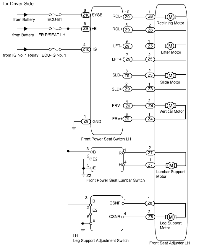
FRONT POWER SEAT CONTROL SYSTEM (w/ Memory) > Front Power Seat does not Operate with Front Power Seat Switch |
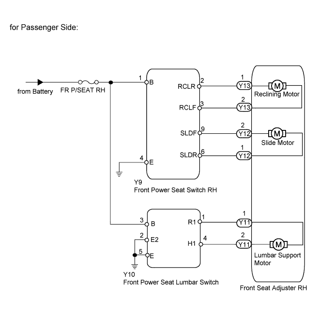
| 1.CHECK SEAT OPERATION |
Operate the power seat switch and check that the front power seat operates.
| Result | Proceed to |
| Driver side power seat does not operate | A |
| Driver side lumbar does not operate | B |
| Driver side leg support does not operate | C |
| Passenger side power seat does not operate | D |
| Passenger side lumbar does not operate | E |
|
| ||||
|
| ||||
|
| ||||
|
| ||||
| A | |
 |
| 2.INSPECT FUSE (ECU-B1, ECU-IG No. 1, FR P/SEAT) |
Remove the ECU-B1 fuse from the engine room relay block.
Remove the FR P/SEAT LH and ECU-IG No. 1 fuses from the main body ECU.
Measure the resistance according to the value(s) in the table below.
| Tester Connection | Condition | Specified Condition |
| ECU-B1 fuse | Always | Below 1 Ω |
| ECU-IG No. 1 fuse | ||
| FR P/SEAT LH fuse |
|
| ||||
| OK | |
|
| 3.CHECK HARNESS AND CONNECTOR (FRONT POWER SEAT SWITCH LH - BATTERY AND BODY GROUND) |
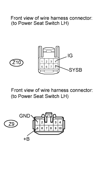 |
Disconnect the Z9 and Z10 switch connectors.
Measure the voltage according to the value(s) in the table below.
| Tester Connection | Switch Condition | Specified Condition |
| Z9-5 (+B) - Body ground | Always | 11 to 14 V |
| Z10-4 (IG) - Body ground | Ignition switch OFF | Below 1 V |
| Ignition switch ON | 11 to 14 V | |
| Z10-8 (SYSB) - Body ground | Always | 11 to 14 V |
Measure the resistance according to the value(s) in the table below.
| Tester Connection | Condition | Specified Condition |
| Z9-1 (GND) - Body ground | Always | Below 1 Ω |
|
| ||||
| OK | |
|
| 4.INSPECT FRONT SEAT ADJUSTER ASSEMBLY LH |
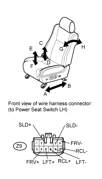 |
Disconnect the Z9 switch connector.
Apply battery voltage and check the operation of the power seat.
| Measurement Condition | Specified Condition |
| Battery positive (+) → Terminal Z9-2 (SLD+) Battery negative (-) → Terminal Z9-3 (SLD-) | Seat slides forward (A) |
| Battery negative (-) → Terminal Z9-2 (SLD+) Battery positive (+) → Terminal Z9-3 (SLD-) | Seat slides rearward (B) |
| Battery positive (+) → Terminal Z9-7 (LFT+) Battery negative (-) → Terminal Z9-9 (LFT-) | Seat cushion rises (C) |
| Battery negative (-) → Terminal Z9-7 (LFT+) Battery positive (+) → Terminal Z9-9 (LFT-) | Seat cushion lowers (D) |
| Battery positive (+) → Terminal Z9-6 (FRV+) Battery negative (-) → Terminal Z9-4 (FRV-) | Seat cushion front rises (E) |
| Battery negative (-) → Terminal Z9-6 (FRV+) Battery positive (+) → Terminal Z9-4 (FRV-) | Seat cushion front lowers (F) |
| Battery positive (+) → Terminal Z9-8 (RCL+) Battery negative (-) → Terminal Z9-10 (RCL-) | Seat tilts forward (G) |
| Battery negative (-) → Terminal Z9-8 (RCL+) Battery positive (+) → Terminal Z9-10 (RCL-) | Seat reclines (H) |
|
| ||||
| OK | ||
 | ||
| ||
| 5.CHECK HARNESS AND CONNECTOR (FRONT POWER SEAT SWITCH LH - POSITION MOTOR) |
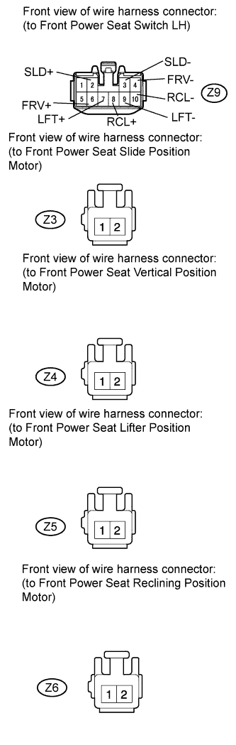 |
Disconnect the Z9 switch connector.
Disconnect the Z3, Z4, Z5 and Z6 motor connectors.
Measure the resistance according to the value(s) in the table below.
| Tester Connection | Condition | Specified Condition |
| Z9-2 (SLD+) - Z3-1 | Always | Below 1 Ω |
| Z9-3 (SLD-) - Z3-2 | ||
| Z9-6 (FRV+) - Z4-1 | ||
| Z9-4 (FRV-) - Z4-2 | ||
| Z9-7 (LFT+) - Z5-2 | ||
| Z9-9 (LFT-) - Z5-1 | ||
| Z9-8 (RCL+) - Z6-2 | ||
| Z9-10 (RCL-) - Z6-1 | ||
| Z9-2 (SLD+) - Body ground | Always | 10 kΩ or higher |
| Z9-3 (SLD-) - Body ground | ||
| Z9-6 (FRV+) - Body ground | ||
| Z9-4 (FRV-) - Body ground | ||
| Z9-7 (LFT+) - Body ground | ||
| Z9-9 (LFT-) - Body ground | ||
| Z9-8 (RCL+) - Body ground | ||
| Z9-10 (RCL-) - Body ground |
|
| ||||
| OK | ||
| ||
| ||
| 6.INSPECT FUSE (FR P/SEAT LH) |
Remove the FR P/SEAT LH fuse from the main body ECU.
Measure the resistance according to the value(s) in the table below.
| Tester Connection | Condition | Specified Condition |
| FR P/SEAT LH fuse | Always | Below 1 Ω |
|
| ||||
| OK | |
|
| 7.INSPECT FRONT POWER SEAT LUMBAR SWITCH |
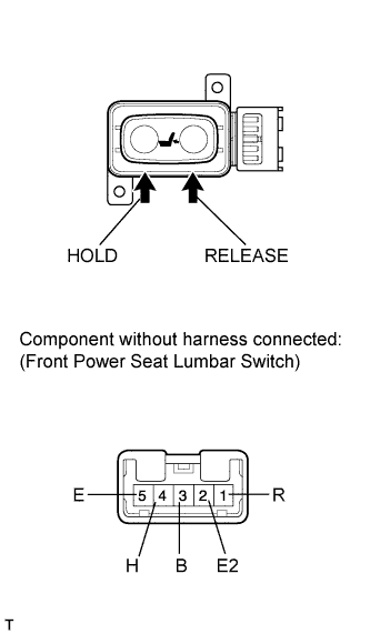 |
Remove the switch (Click here).
Measure the resistance according to the value(s) in the table below.
| Tester Connection | Switch Condition | Specified Condition |
| 3 (B) - 4 (H) | HOLD | Below 1 Ω |
| 1 (R) - 2 (E2) | ||
| 1 (R) - 2 (E2) | OFF | |
| 4 (H) - 5 (E) | ||
| 1 (R) - 3 (B) | RELEASE | |
| 4 (H) - 5 (E) |
|
| ||||
| OK | |
|
| 8.INSPECT FRONT SEAT ADJUSTER ASSEMBLY LH |
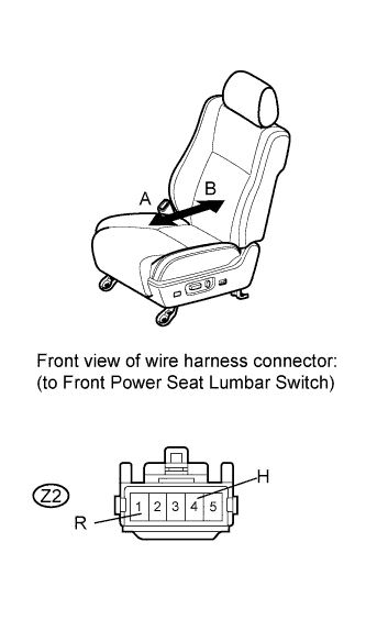 |
Disconnect the Z2 switch connector.
Apply battery voltage and check the operation of the power seat.
| Measurement Condition | Specified Condition |
| Battery positive (+) → Terminal Z2-4 (H) Battery negative (-) → Terminal Z2-1 (R) | Lumbar support moves forward (A) |
| Battery negative (-) → Terminal Z2-4 (H) Battery positive (+) → Terminal Z2-1 (R) | Lumbar support moves rearward (B) |
|
| ||||
| OK | ||
| ||
| ||
| 9.CHECK HARNESS AND CONNECTOR (FRONT POWER SEAT LUMBAR SWITCH - LUMBAR SUPPORT MOTOR LH) |
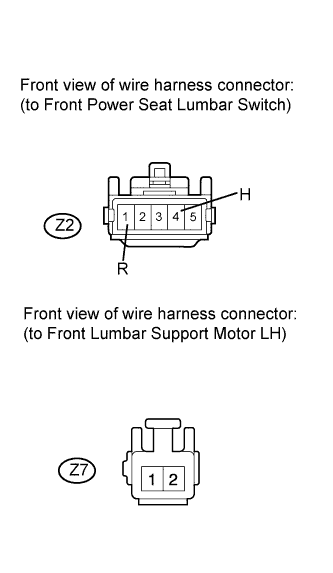 |
Disconnect the Z2 switch connector.
Disconnect the Z7 motor connector.
Measure the resistance according to the value(s) in the table below.
| Tester Connection | Condition | Specified Condition |
| Z2-1 (R) - Z7-2 | Always | Below 1 Ω |
| Z2-4 (H) - Z7-1 | Always | |
| Z2-1 (R) - Body ground | Always | 10 kΩ or higher |
| Z2-4 (H) - Body ground | Always |
|
| ||||
| OK | ||
| ||
| ||
| 10.INSPECT FUSE (FR P/SEAT LH) |
Remove the FR P/SEAT LH fuse from the main body ECU.
Measure the resistance according to the value(s) in the table below.
| Tester Connection | Condition | Specified Condition |
| FR P/SEAT LH fuse | Always | Below 1 Ω |
|
| ||||
| OK | |
|
| 11.INSPECT LEG SUPPORT ADJUSTMENT SWITCH |
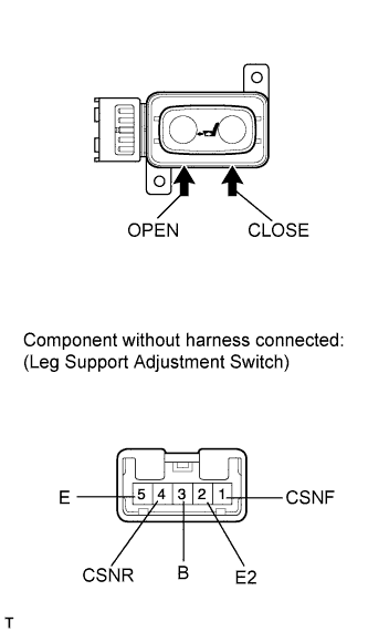 |
Remove the switch (Click here).
Measure the resistance according to the value(s) in the table below.
| Tester Connection | Switch Condition | Specified Condition |
| 1 (CSNF) - 3 (B) | OPEN | Below 1 Ω |
| 4 (CSNR) - 5 (E) | ||
| 1 (CSNF) - 2 (E2) | OFF | |
| 4 (CSNR) - 5 (E) | ||
| 1 (CSNF) - 2 (E2) | CLOSE | |
| 3 (B) - 4 (CSNR) |
|
| ||||
| OK | |
|
| 12.INSPECT FRONT SEAT ADJUSTER ASSEMBLY LH |
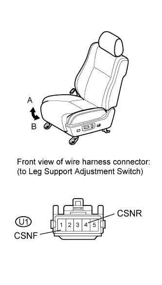 |
Disconnect the U1 switch connector.
Apply battery voltage and check the operation of the power seat.
| Measurement Condition | Specified Condition |
| Battery positive (+) → Terminal U1-4 (CSNR) Battery negative (-) → Terminal U1-1 (CSNF) | Leg support opens (A) |
| Battery negative (-) → Terminal U1-4 (CSNR) Battery positive (+) → Terminal U1-1 (CSNF) | Leg support closes (B) |
|
| ||||
| OK | ||
| ||
| ||
| 13.CHECK HARNESS AND CONNECTOR (LEG SUPPORT ADJUSTMENT SWITCH - LEG SUPPORT MOTOR LH) |
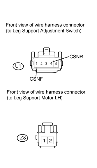 |
Disconnect the U1 switch connector.
Disconnect the Z8 motor connector.
Measure the resistance according to the value(s) in the table below.
| Tester Connection | Condition | Specified Condition |
| U1-1 (CSNF) - Z8-1 | Always | Below 1 Ω |
| U1-4 (CSNR) - Z8-2 | ||
| U1-1 (CSNF) - Body ground | Always | 10 kΩ or higher |
| U1-4 (CSNR) - Body ground |
|
| ||||
| OK | ||
| ||
| ||
| 14.INSPECT FUSE (FR P/SEAT RH) |
Remove the FR P/SEAT RH fuse from the main body ECU.
Measure the resistance according to the value(s) in the table below.
| Tester Connection | Condition | Specified Condition |
| FR P/SEAT RH fuse | Always | Below 1 Ω |
|
| ||||
| OK | |
|
| 15.INSPECT FRONT POWER SEAT SWITCH RH |
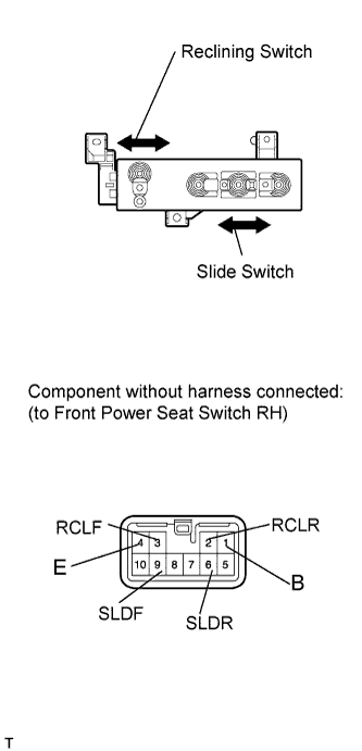 |
Remove the switch (Click here)
Measure the resistance according to the value(s) in the table below.
| Tester Connection | Switch Condition | Specified Condition |
| 9 (SLDF) - 1 (B) | FRONT | Below 1 Ω |
| 6 (SLDR) - 4 (E) | ||
| 9 (SLDF) - 4 (E) | OFF | |
| 6 (SLDR) - 4 (E) | ||
| 9 (SLDF) - 4 (E) | REAR | |
| 6 (SLDR) - 1 (B) |
| Tester Connection | Switch Condition | Specified Condition |
| 3 (RCLF) - 1 (B) | FRONT | Below 1 Ω |
| 2 (RCLR) - 4 (E) | ||
| 3 (RCLF) - 4 (E) | OFF | |
| 2 (RCLR) - 4 (E) | ||
| 3 (RCLF) - 4 (E) | REAR | |
| 2 (RCLR) - 1 (B) |
|
| ||||
| OK | |
|
| 16.INSPECT FRONT SEAT ADJUSTER ASSEMBLY RH |
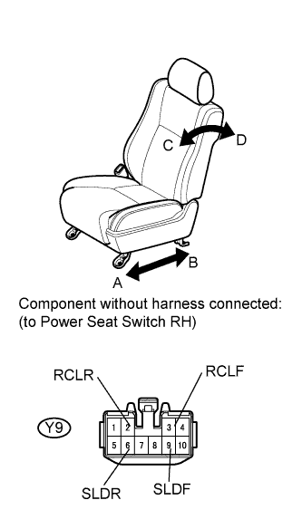 |
Disconnect the Y9 switch connector.
Apply battery voltage and check the operation of the power seat.
| Measurement Condition | Specified Condition |
| Battery positive (+) → Terminal 9 (SLDF) Battery negative (-) → Terminal 6 (SLDR) | Seat slides forward (A) |
| Battery negative (-) → Terminal 9 (SLDF) Battery positive (+) → Terminal 6 (SLDR) | Seat slides rearward (B) |
| Battery positive (+) → Terminal 3 (RCLF) Battery negative (-) → Terminal 2 (RCLR) | Seat tilts forward (C) |
| Battery negative (-) → Terminal 3 (RCLF) Battery positive (+) → Terminal 2 (RCLR) | Seat reclines (D) |
|
| ||||
| OK | ||
| ||
| ||
| 17.CHECK HARNESS AND CONNECTOR (FRONT POWER SEAT SWITCH RH - POSITION MOTOR) |
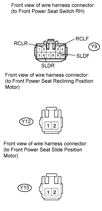 |
Disconnect the Y9 switch connector.
Disconnect the Y12 and Y13 motor connectors.
Measure the resistance according to the value(s) in the table below.
| Tester Connection | Condition | Specified Condition |
| Y9-9 (SLDF) -Y12-2 | Always | Below 1 Ω |
| Y9-6 (SLDR) - Y12-1 | ||
| Y9-3 (RCLF) - Y13-2 | ||
| Y9-2 (RCLR) - Y13-1 | ||
| Y9-9 (SLDF) - Body ground | Always | 10 kΩ or higher |
| Y9-6 (SLDR) - Body ground | ||
| Y9-3 (RCLF) - Body ground | ||
| Y9-2 (RCLR) - Body ground |
|
| ||||
| OK | ||
| ||
| ||
| 18.INSPECT FUSE (FR P/SEAT RH) |
Remove the FR P/SEAT RH fuse from the main body ECU.
Measure the resistance according to the value(s) in the table below.
| Tester Connection | Condition | Specified Condition |
| FR P/SEAT RH fuse | Always | Below 1 Ω |
|
| ||||
| OK | |
|
| 19.INSPECT FRONT POWER SEAT LUMBAR SWITCH |
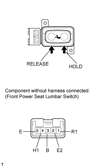 |
Remove the switch (Click here).
Measure the resistance according to the value(s) in the table below.
| Tester Connection | Switch Condition | Specified Condition |
| 3 (B) - 4 (H1) | HOLD | Below 1 Ω |
| 1 (R1) - 2 (E2) | ||
| 1 (R1) - 2 (E2) 4 (H1) - 5 (E) | OFF | |
| 1 (R1) - 3 (B) | RELEASE | |
| 4 (H1) - 5 (E) |
|
| ||||
| OK | |
|
| 20.INSPECT FRONT SEAT ADJUSTER ASSEMBLY RH |
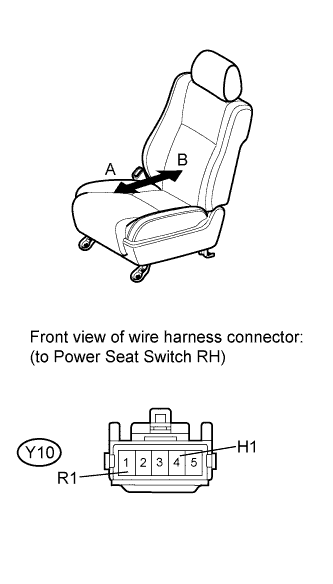 |
Disconnect the Y10 switch connector.
Apply battery voltage and check the operation of the power seat.
| Measurement Condition | Specified Condition |
| Battery positive (+) → Terminal Y10-4 (H1) Battery negative (-) → Terminal Y10-1 (R1) | Lumbar support moves forward (A) |
| Battery negative (-) → Terminal Y10-4 (H1) Battery positive (+) → Terminal Y10-1 (R1) | Lumbar support moves rearward (B) |
|
| ||||
| OK | ||
| ||
| ||
| 21.CHECK HARNESS AND CONNECTOR (FRONT POWER SEAT LUMBAR SWITCH - LUMBAR SUPPORT MOTOR RH) |
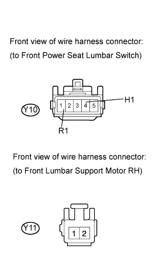 |
Disconnect the Y10 switch connector.
Disconnect the Y11 motor connector.
Measure the resistance according to the value(s) in the table below.
| Tester Connection | Condition | Specified Condition |
| Y10-1 (R1) - Y11-1 | Always | Below 1 Ω |
| Y10-4 (H1) - Y11-2 | ||
| Y10-1 (R1) - Body ground | Always | 10 kΩ or higher |
| Y10-4 (H1) - Body ground |
|
| ||||
| OK | ||
| ||
| ||

