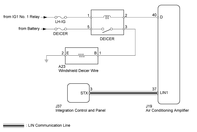
WINDSHIELD DEICER SYSTEM > Windshield Deicer does not Operate |
| 1.PERFORM ACTIVE TEST USING TECHSTREAM (DEICER RELAY) |
Select the Active Test using the Techstream to generate a control command, and then check that the windshield deicer operates.
| Tester Display | Test Part | Control Range | Diagnostic Note |
| Deicer Relay (Front) | Deicer relay operation | OFF or ON | - |
|
| ||||
| OK | |
 |
| 2.CHECK INTEGRATION CONTROL AND PANEL (OPERATION) |
Temporarily replace the integration control and panel with a new or normally functioning one.
For Column Shift Type, refer to the following procedures (Click here).
For Floor Shift Type, refer to the following procedures (Click here).
Check that the malfunction disappears.
|
| ||||
| OK | ||
 | ||
| ||
| 3.INSPECT FUSE (DEICER) |
Remove the DEICER fuse from the engine room relay block.
Measure the resistance according to the value(s) in the table below.
| Tester Connection | Condition | Specified Condition |
| DEICER fuse | Always | Below 1 Ω |
|
| ||||
| OK | |
|
| 4.INSPECT DEICER RELAY |
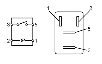 |
Remove the DEICER relay from the engine room relay block.
Measure the resistance according to the value(s) in the table below.
| Tester Connection | Condition | Specified Condition |
| 3 - 5 | When battery voltage is not applied between terminals 1 and 2 | 10 kΩ or higher |
| When battery voltage is applied to terminals 1 and 2 | Below 1 Ω |
|
| ||||
| OK | |
|
| 5.CHECK HARNESS AND CONNECTOR (DEICER RELAY - AIR CONDITIONING AMPLIFIER AND BATTERY) |
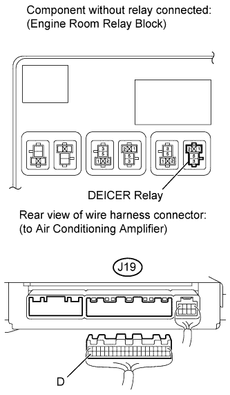 |
Remove the DEICER relay from the engine room relay block.
Disconnect the J19 air conditioning amplifier connector.
Measure the voltage according to the value(s) in the table below.
| Tester Connection | Condition | Specified Condition |
| DEICER relay terminal 1 - Body ground | Ignition switch ON | 11 to 14 V |
| DEICER relay terminal 5 - Body ground | Always | 11 to 14 V |
Measure the resistance according to the value(s) in the table below.
| Tester Connection | Condition | Specified Condition |
| DEICER relay terminal 2 - J19-40 (D) | Always | Below 1 Ω |
| DEICER relay terminal 2 - Body ground | Always | 10 kΩ or higher |
|
| ||||
| OK | |
|
| 6.CHECK HARNESS AND CONNECTOR (DEICER RELAY - WINDSHIELD DEICER WIRE) |
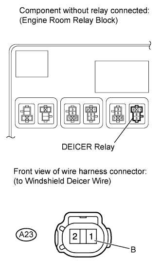 |
Remove the DEICER relay from the engine room relay block.
Disconnect the A23 windshield deicer wire connector.
Measure the resistance according to the value(s) in the table below.
| Tester Connection | Condition | Specified Condition |
| A23-1 (B) - DEICER relay terminal 3 | Always | Below 1 Ω |
| DEICER relay terminal 3 - Body ground | Always | 10 kΩ or higher |
|
| ||||
| OK | |
|
| 7.CHECK HARNESS AND CONNECTOR (WINDSHIELD DEICER WIRE - BODY GROUND) |
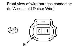 |
Disconnect the A23 windshield deicer wire connector.
Measure the resistance according to the value(s) in the table below.
| Tester Connection | Condition | Specified Condition |
| A23-2 (E) - Body ground | Always | Below 1 Ω |
|
| ||||
| OK | |
|
| 8.CHECK WINDSHIELD DEICER WIRE |
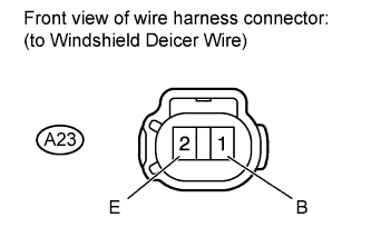 |
Disconnect the A23 windshield deicer wire connector.
Measure the voltage according to the value(s) in the table below.
| Tester Connection | Condition | Specified Condition |
| A23-1 (B) - A23-2 (E) | Ignition switch ON Windshield deicer switch ON | 11 to 14 V |
|
| ||||
| OK | ||
| ||
| ||

