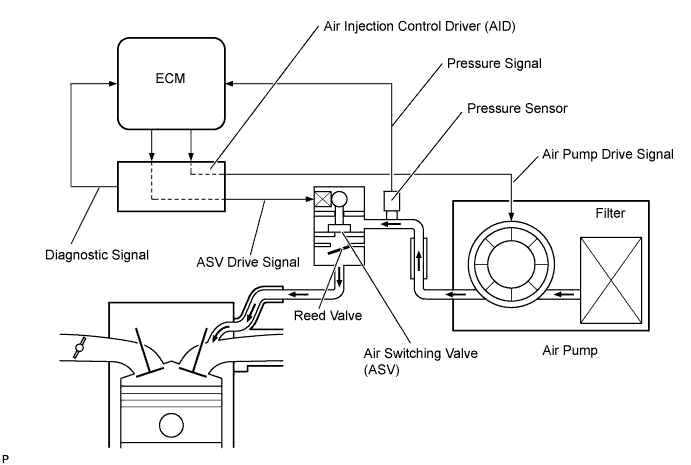
DTC P2431 Secondary Air Injection System Air Flow / Pressure Sensor Circuit Range / Performance Bank1 |
DTC P2432 Secondary Air Injection System Air Flow / Pressure Sensor Circuit Low Bank1 |
DTC P2433 Secondary Air Injection System Air Flow / Pressure Sensor Circuit High Bank1 |
DTC P2436 Secondary Air Injection System Air Flow / Pressure Sensor Circuit Bank2 |
DTC P2437 Open in Secondary Air Injection System Air Flow / Pressure Sensor Circuit Bank2 |
DTC P2438 Short in Secondary Air Injection System Air Flow / Pressure Sensor Circuit Bank2 |
| DTC No. | DTC Detection Condition | Trouble Area |
| P2431 P2436 | Pressure sensor indicates less than 45.6 kPa (342 mmHg), or more than 135 kPa (1013 mmHg) (2 trip detection logic) |
|
| P2432 P2437 | While engine running, voltage output of pressure sensor remains below 0.5 V (1 trip detection logic) |
|
| P2433 P2438 | While engine running, voltage output of pressure sensor remains above 4.5 V (1 trip detection logic) |
|
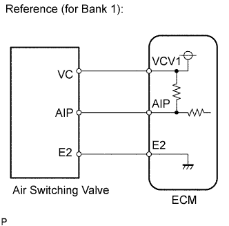
| Related DTCs | P2431: Air flow/Pressure sensor circuit rationality P2432: Air flow/Pressure sensor circuit range check (Low voltage) P2433: Air flow/Pressure sensor circuit range check (High voltage) P2436: Air flow/Pressure sensor circuit rationality P2437: Air flow/Pressure sensor circuit range check (Low voltage) P2438: Air flow/Pressure sensor circuit range check (High voltage) |
| Required Sensors/Components (Main) | Pressure sensor |
| Required Sensors/Components (Related) | - |
| Frequency of Operation | Continuous |
| Duration | P2432, P2433, P2437, P2438: 0.5 seconds P2431, P2436: 5 seconds |
| MIL Operation | P2432, P2433, P2437, P2438: Immediate P2431, P2436: 2 driving cycles |
| Sequence of Operation | None |
| Monitor runs whenever following DTCs not present | P2432, P2433, P2437, P2438 (AIR pressure sensor - Low/High) |
| Starter | OFF |
| Battery voltage | 8 V or more |
| Ignition switch | ON |
| Monitor runs whenever following DTCs not present | None |
| All of following conditions met: | - |
| Starter | OFF |
| Battery voltage | 8 V or more |
| Ignition switch | ON |
| Air pressure | Less than 45.63 kPa (342 mmHg), or more than 135 kPa (1013 mmHg) |
| Air pressure sensor voltage | Less than 0.5 V |
| Air pressure sensor voltage | More than 4.5 V |
| Air pressure sensor voltage | Between 0.5 V and 4.5 V |
| Tester Display | Description |
| NORMAL |
|
| ABNORMAL |
|
| INCOMPLETE |
|
| N/A |
|
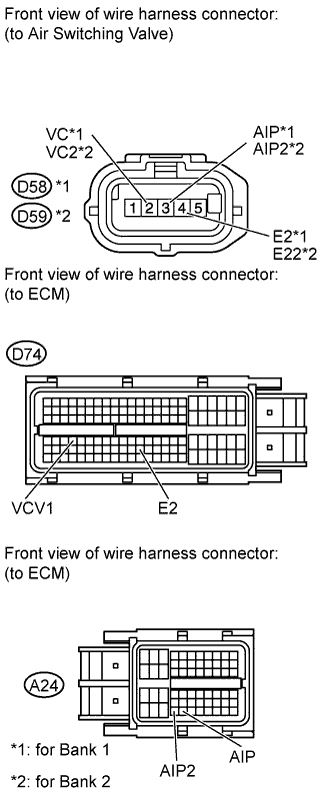
| 1.CHECK HARNESS AND CONNECTOR (AIR SWITCHING VALVE - ECM) |
 |
Disconnect the air switching valve connector.
Disconnect the ECM connectors.
Measure the resistance according to the value(s) in the table below.
| Tester Connection | Condition | Specified Condition |
| D58-3 (AIP) - A24-54 (AIP) | Always | Below 1 Ω |
| D58-2 (VC) - D74-67 (VCV1) | Always | Below 1 Ω |
| D58-4 (E2) - D74-98 (E2) | Always | Below 1 Ω |
| D59-3 (AIP2) - A24-53 (AIP2) | Always | Below 1 Ω |
| D59-2 (VC2) - D74-67 (VCV1) | Always | Below 1 Ω |
| D59-4 (E22) - D74-98 (E2) | Always | Below 1 Ω |
| D58-3 (AIP) or A24-54 (AIP) - Body ground | Always | 10 kΩ or higher |
| D58-2 (VC) or D74-67 (VCV1) - Body ground | Always | 10 kΩ or higher |
| D59-3 (AIP2) or A24-53 (AIP2) - Body ground | Always | 10 kΩ or higher |
| D59-2 (VC2) or D74-67 (VCV1) - Body ground | Always | 10 kΩ or higher |
|
| ||||
| OK | |
 |
| 2.INSPECT AIR SWITCHING VALVE ASSEMBLY (PRESSURE SENSOR) |
Connect the Techstream to the DLC3.
Turn the ignition switch to ON.
Turn the Techstream on.
Enter the following menus: Powertrain / Engine and ECT / Data List / Air pump pressure (Absolute) and Air Pump2 Pressure (Absolute).
Check the pressure displayed on the Techstream.
| Result | Proceed to |
| OK | A |
| NG (for Bank 1) | B |
| NG (for Bank 2) | C |
|
| ||||
|
| ||||
| A | ||
 | ||
| ||
