ROOF HEADLINING (for Double Cab) > INSTALLATION |
| 1. INSTALL ROOF HEADLINING ASSEMBLY |
|
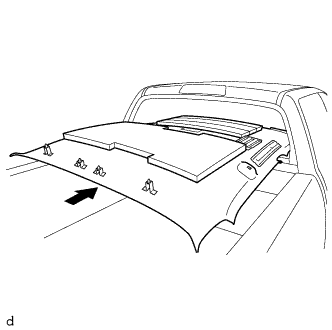
Place the roof headlining assembly into the cabin as shown in the illustration.
Attach the 4 clips to install the roof headlining assembly.
Attach the 4 wire harness clamps and connect the connector to the front pillar LH.
w/ EC Mirror:
Connect the connector.
| 2. INSTALL COAT HOOK |
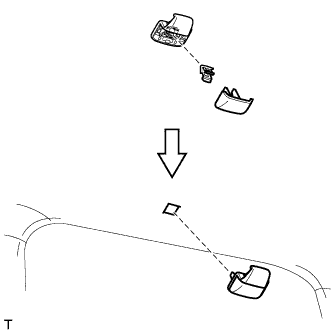 |
Assemble the coat hook as shown in the illustration.
Attach the clip to install the coat hook.
| 3. INSTALL ASSIST GRIP SUB-ASSEMBLY |
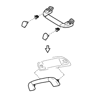 |
Assemble the assist grip sub-assembly as shown in the illustration.
Attach the 2 clips to install the assist grip sub-assembly.
| 4. INSTALL BACK WINDOW ASSEMBLY |
for Fixed Type:
(Click here)
for Slide Type:
(Click here)
for Power Slide Type:
(Click here)
| 5. INSTALL VISOR HOLDER |
Using a T20 "TORX" driver, install the visor holder with the "TORX "screw.
| 6. INSTALL VISOR ASSEMBLY LH |
w/ Vanity Light:
Connect the connector.
Attach the claw to install the visor assembly LH.
Install the 2 screws.
| 7. INSTALL VISOR ASSEMBLY RH |
| 8. INSTALL ROOM LIGHT ASSEMBLY |
Attach the 3 guides and 2 clips to install the No. 1 room light assembly.
Attach the 2 guides and 4 claws to install the No. 1 room light lens.
| 9. INSTALL INNER REAR VIEW MIRROR STAY HOLDER COVER (w/ EC Mirror) |
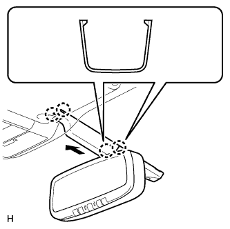 |
Attach the 2 claws of the inner rear view mirror stay holder cover to the mirror, and then slide the inner rear view mirror stay holder cover in the direction indicated by the arrow in the illustration to attach the 2 claws to the roof headlining and install the inner rear view mirror stay holder cover.
| 10. INSTALL ROOF CONSOLE BOX ASSEMBLY |
Connect the connector.
Using a T20 "TORX" driver, install the roof console box assembly with the 4 "TORX" screws.
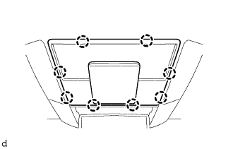 |
Attach the 8 claws to install the roof console box base.
| 11. INSTALL FRONT QUARTER TRIM PANEL ASSEMBLY LH |
Pass the rear seat outer belt assembly through the hole of the front quarter trim panel assembly LH.
Attach the 4 clips to install the front quarter trim panel assembly LH.
Install the 2 bolts.
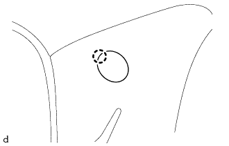 |
Attach the claw to close the cover.
| 12. INSTALL FRONT QUARTER TRIM PANEL ASSEMBLY RH |
| 13. INSTALL LOWER QUARTER TRIM PANEL ASSEMBLY LH |
Attach the 6 clips to install the lower quarter trim panel assembly LH.
Connect the rear seat outer belt assembly with the bolt.
Attach the 2 claws to install the cover.
| 14. INSTALL LOWER QUARTER TRIM PANEL ASSEMBLY RH |
| 15. INSTALL FRONT SHOULDER BELT ANCHOR PLATE SUB-ASSEMBLY LH |
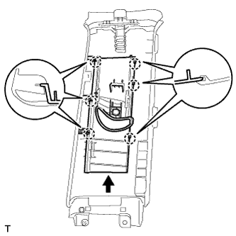 |
Slide the front shoulder belt anchor plate sub-assembly LH in the direction of the arrow and attach the 6 claws to install it.
| 16. INSTALL FRONT SHOULDER BELT ANCHOR PLATE SUB-ASSEMBLY RH |
| 17. INSTALL CENTER PILLAR GARNISH LH |
Pass the front seat outer belt assembly LH through the hole of the center pillar garnish LH.
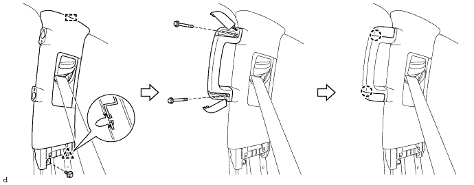
Attach the guide and clip to install the center pillar garnish LH.
Install the bolt.
Install the rear assist grip assembly to the center pillar garnish LH with the 2 bolts.
Attach the 2 claws to close the 2 assist grip covers.
| 18. INSTALL CENTER PILLAR GARNISH RH |
| 19. INSTALL LOWER CENTER PILLAR GARNISH LH |
Attach the 7 clips and 2 claws to install the lower center pillar garnish LH.
Connect the front seat outer belt assembly LH with the bolt.
Attach the 2 claws to install the cover.
| 20. INSTALL LOWER CENTER PILLAR GARNISH RH |
| 21. INSTALL FRONT PILLAR GARNISH LH |
Attach the clip to install the front pillar garnish LH.
Install the bolt.
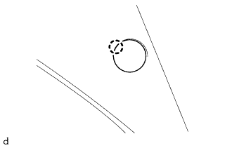 |
Attach the claw to close the cover.
| 22. INSTALL FRONT PILLAR GARNISH RH |
Attach the clip to install the front pillar garnish RH.
Install the front assist grip sub-assembly to the front pillar garnish RH with the 2 bolts.
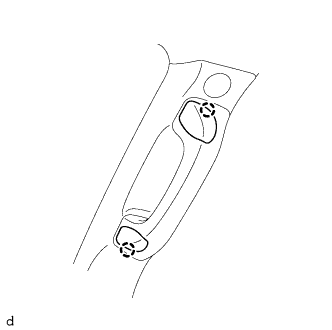 |
Attach the 2 claws to close the 2 assist grip covers.
| 23. INSTALL REAR DOOR OPENING TRIM WEATHERSTRIP LH |
Install the rear door opening trim weatherstrip LH.
| 24. INSTALL REAR DOOR OPENING TRIM WEATHERSTRIP RH |
| 25. INSTALL FRONT DOOR OPENING TRIM WEATHERSTRIP LH |
Install the front door opening trim weatherstrip LH.
| 26. INSTALL FRONT DOOR OPENING TRIM WEATHERSTRIP RH |
| 27. INSTALL COWL SIDE TRIM BOARD LH |
Attach the 2 clips to install the cowl side trim board LH.
Install the nut.
| 28. INSTALL COWL SIDE TRIM BOARD RH |
| 29. INSTALL REAR DOOR SCUFF PLATE LH |
Attach the 6 claws and 2 clips to install the rear door scuff plate LH.
| 30. INSTALL REAR DOOR SCUFF PLATE RH |
| 31. INSTALL FRONT DOOR SCUFF PLATE LH |
Attach the 6 claws and 3 clips to install the front door scuff plate LH.
| 32. INSTALL FRONT DOOR SCUFF PLATE RH |
| 33. INSTALL REAR SEAT ASSEMBLY |
| 34. INSTALL FRONT SEAT ASSEMBLY (for Center Seat) |
| 35. INSTALL FRONT SEAT ASSEMBLY (for Manual Seat) |
| 36. INSTALL FRONT SEAT ASSEMBLY (for Power Seat) |
| 37. CONNECT CABLE TO NEGATIVE BATTERY TERMINAL |
| 38. CHECK SRS WARNING LIGHT |