TRANSMISSION CONTROL CABLE (for Column Shift Type) > INSTALLATION |
| 1. INSTALL COLUMN SHIFT TRANSMISSION CONTROL CABLE ASSEMBLY |
|
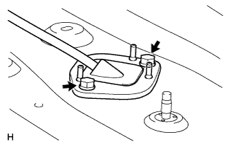
Insert the transmission control cable from the vehicle interior, and install the cable retainer with the 2 bolts.
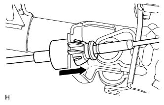 |
Connect the cable to the steering column shaft bracket so that the claws of the outer cable socket are securely attached.
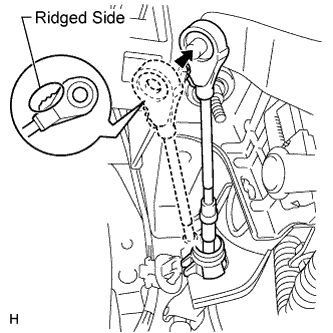 |
Connect the column shift transmission control cable end to the column shift.
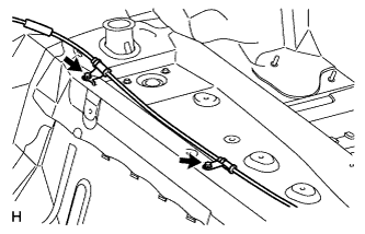 |
Connect the 2 cable clamps with the 2 bolts.
Return the floor carpet to its original position.
Move the shift lever to N.
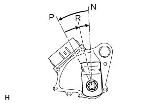 |
Turn the control shaft lever counterclockwise until it stops, and then turn it clockwise 2 notches to set it to the N position.
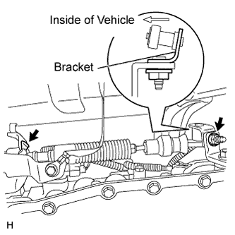 |
Connect the control cable with a new clip and the nut.
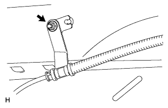 |
Connect the transmission control cable support with the nut.
| 2. INSTALL FRONT SEAT ASSEMBLY LH |
for Manual Seat Type:
Install the front seat LH (Click here).
for Power Seat Type:
Install the front seat LH (Click here).
for Center Seat:
Install the front seat LH (Click here).
| 3. ADJUST SHIFT LEVER POSITION |
Move the shift lever to N.
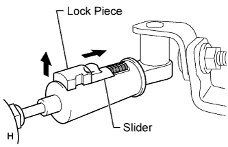 |
Fold back the transmission control cable adjust case cover. Then while sliding the slider toward the cable end side, press out the lock piece from the back side to release the lock.
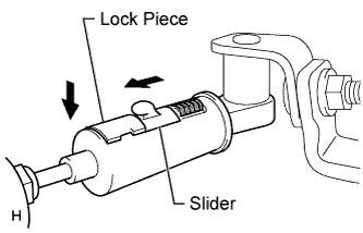 |
Check that the spring of the adjust case is applying enough tension to the shift control cable. Then press in the lock piece to set the lock.
Return the cover of the adjust case to its original position.
Inspect the shift lever operation after the adjustment.
| 4. INSPECT SHIFT LEVER POSITION |
When moving the shift lever from N to other positions, check that the lever can be moved smoothly and accurately to each position and that the position indicator comes on in accordance with the shift lever position.
If the indicator and shift lever position do not match, carry out the following adjustment procedures.
| 5. INSTALL UPPER STEERING COLUMN COVER |
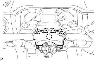 |
Attach the claw to install the upper steering column cover.
Attach the 4 clips.
| 6. INSTALL LOWER STEERING COLUMN COVER |
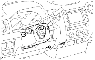 |
Attach the 2 claws to install the lower steering column cover.
Install the 2 screws.
| 7. INSTALL CENTER LOWER INSTRUMENT COVER |
Attach the 2 guides and 2 clips to install the lower center instrument cover.
Install the 2 clips.
| 8. INSTALL LOWER NO. 1 INSTRUMENT PANEL AIRBAG ASSEMBLY |
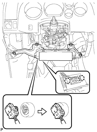 |
Connect the connector.
Attach the 2 claws to install the DLC3.
Install the 4 bolts to install the instrument panel airbag.
| 9. INSTALL LOWER INSTRUMENT PANEL FINISH PANEL SUB-ASSEMBLY LH |
Connect the hood lock control cable to the hood lock control lever, rotate the hood lock control cable, and then slide and push the hood lock control cable into place.
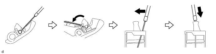
Attach the 3 hooks to connect the hood lock control lever to the lower instrument panel finish panel sub-assembly LH.
Connect each connector.
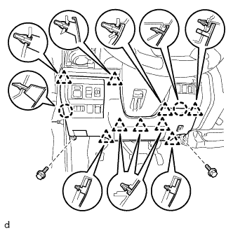 |
Attach the 9 clips and 2 claws to install the lower instrument panel finish panel sub-assembly LH.
Install the 2 bolts <A>.
| 10. INSTALL COWL SIDE TRIM BOARD LH |
Attach the 2 clips to install the cowl side trim board LH.
Install the nut.
| 11. INSTALL FRONT DOOR SCUFF PLATE LH (for Double Cab, CrewMax) |
Attach the 6 claws and 3 clips to install the front door scuff plate LH.
| 12. INSTALL FRONT DOOR SCUFF PLATE LH (for Regular Cab) |
Attach the 6 claws and 3 clips to install the front door scuff plate LH.
| 13. INSTALL STEERING WHEEL ASSEMBLY |