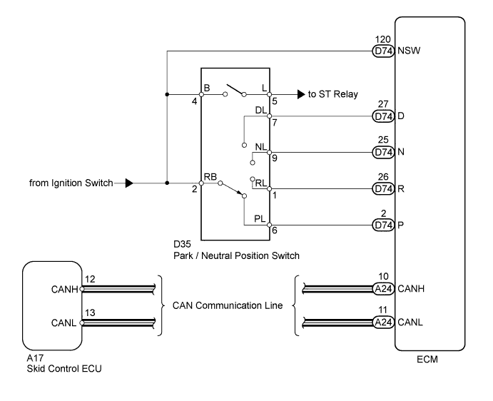
DTC C1207/37 Malfunction in Park / Neutral Position Switch |
| DTC Code | DTC Detection Condition | Trouble Area |
| C1207/37 | When all conditions below are met:
|
|
| 1.CHECK CAN COMMUNICATION SYSTEM |
Check if a CAN communication system DTC is output (Click here).
| Result | Proceed to |
| DTC is not output | A |
| DTC is output | B |
|
| ||||
| A | |
 |
| 2.INSPECT PARK / NEUTRAL POSITION SWITCH ASSEMBLY |
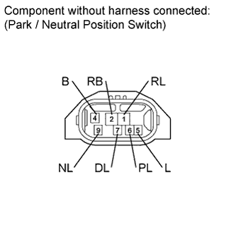 |
Disconnect the D35 switch connector.
Measure the resistance of the park / neutral position switch when the shift lever is moved to each position.
| Tester Connection | Switch Condition | Specified Condition |
| 2 (RB) - 6 (PL) 4 (B) - 5 (L) | Shift lever position on P | Below 1 Ω |
| 2 (RB) - 1 (RL) | Shift lever position on R | |
| 2 (RB) - 9 (NL) 4 (B) - 5 (L) | Shift lever position on N | |
| 2 (RB) - 7 (DL) | Shift lever position on D Shift lever position on S, "+" and "-" | |
| 2 (RB) - 6 (PL) 4 (B) - 5 (L) | Shift lever position not on P | 10 kΩ or higher |
| 2 (RB) - 1 (RL) | Shift lever position not on R | |
| 2 (RB) - 9 (NL) 4 (B) - 5 (L) | Shift lever position not on N | |
| 2 (RB) - 7 (DL) | Shift lever position not on D Shift lever position not on S, "+" and "-" |
|
| ||||
| OK | |
|
| 3.CHECK PARK / NEUTRAL POSITION SWITCH ASSEMBLY (POWER SOURCE) |
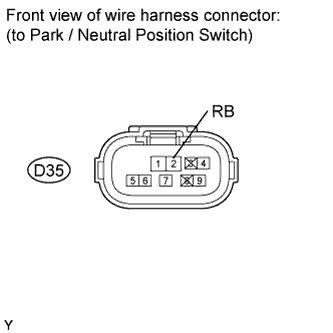 |
Disconnect the D35 switch connector.
Measure the voltage according to the value(s) in the table below.
| Tester Connection | Switch Condition | Specified Condition |
| D35-2 (RB) - Body ground | Ignition switch ON | 11 to 14 V |
| D35-2 (RB) - Body ground | Ignition switch off | Below 1 V |
|
| ||||
| OK | |
|
| 4.CHECK HARNESS AND CONNECTOR (PARK / NEUTRAL POSITION SWITCH - ECM) |
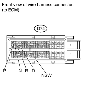 |
Disconnect the D74 ECM connector.
Measure the voltage according to the value(s) in the table below.
| Tester Connection | Switch Condition | Specified Condition |
| D74-2 (P) - Body ground D74-120 (NSW) - Body ground | Ignition switch ON Shift lever position on P | 11 to 14 V |
| D74-26 (R) - Body ground | Ignition switch ON Shift lever position on R | 11 to 14 V* |
| D74-25 (N) - Body ground D74-120 (NSW) - Body ground | Ignition switch ON Shift lever position on N | 11 to 14 V |
| D74-27 (D) - Body ground | Ignition switch ON Shift lever position on D | |
| D74-2 (P) - Body ground D74-120 (NSW) - Body ground | Ignition switch ON Shift lever position not on P | Below 1 V |
| D74-26 (R) - Body ground | Ignition switch ON Shift lever position not on R | |
| D74-25 (N) - Body ground D74-120 (NSW) - Body ground | Ignition switch ON Shift lever position not on N | |
| D74-27 (D) - Body ground | Ignition switch ON Shift lever position not on D |
| Result | Proceed to |
| NG | A |
| OK (for 1GR-FE) | B |
| OK (for 1UR-FE) | C |
| OK (for 3UR-FE) | D |
| OK (for 3UR-FBE) | E |
|
| ||||
|
| ||||
|
| ||||
|
| ||||
| A | ||
 | ||
| ||
