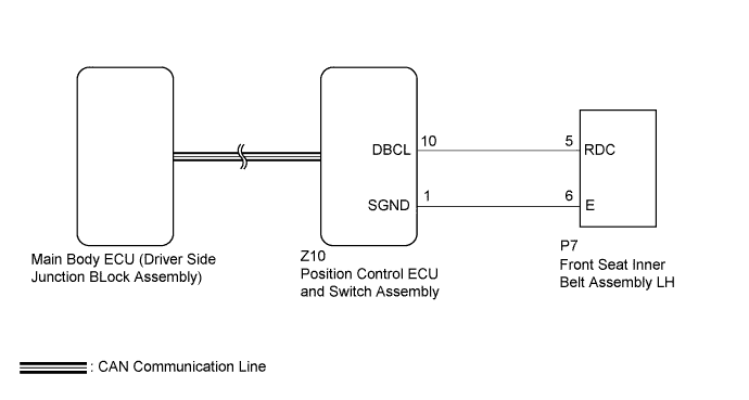
FRONT POWER SEAT CONTROL SYSTEM (w/ Memory) > Power Seat Power Easy Access System Function does not Operate |
| 1.CHECK CAN COMMUNICATION SYSTEM |
Use the Techstream to check if the CAN communication system is functioning normally (Click here).
|
| ||||
| OK | |
 |
| 2.CHECK FRONT POWER SEAT OPERATION |
Check that each function of the power seat operates normally by using the front power seat switches (Click here).
| Result | Proceed to |
| Power seat functions operate normally | A |
| All power seat functions do not operate | B |
| One or more power seat motors do not operate | C |
|
| ||||
|
| ||||
| A | |
|
| 3.CHECK SEAT POSITION MEMORY FUNCTION |
Perform a memory operation and check that the buzzer sounds to indicate the completion of the memory operation (Click here).
|
| ||||
| OK | |
|
| 4.READ VALUE USING TECHSTREAM (DRIVER SEAT BUCKLE SW) |
Connect the Techstream to the DLC3.
Turn the ignition switch to ON.
Turn the Techstream on.
Enter the following menus: Body Electrical / Driver Seat / Data List.
Read the Data List according to the display on the Techstream.
| Tester Display | Measurement Item/Range | Normal Condition | Diagnostic Note |
| Driver Seat Buckle SW | Status of the driver seat belt / ON or OFF | ON: Tongue plate is engaged OFF: Tongue plate is not engaged | - |
|
| ||||
| OK | |
|
| 5.REPLACE POSITION CONTROL ECU AND SWITCH ASSEMBLY |
Temporarily replace the position control ECU and switch assembly with a new or normally functioning one (Click here).
| NEXT | |
|
| 6.CHECK POWER SEAT POWER EASY ACCESS SYSTEM |
Check that the power seat easy access system operates normally when engaging and disengaging the tongue plate of the front seat inner belt with the shift lever in P (Click here).
|
| ||||
| OK | ||
 | ||
| ||
| 7.INSPECT FRONT SEAT INNER BELT ASSEMBLY LH |
Remove the front seat inner belt assembly LH (Click here).
Inspect the front seat inner belt assembly LH (Click here).
|
| ||||
| OK | |
|
| 8.CHECK HARNESS AND CONNECTOR (POSITION CONTROL ECU AND SWITCH ASSEMBLY - FRONT SEAT INNER BELT ASSEMBLY LH) |
Disconnect the Z10 position control ECU and switch assembly connector.
Disconnect the P7 front seat inner belt assembly LH connector.
Measure the resistance according to the value(s) in the table below.
| Tester Connection | Condition | Specified Condition |
| Z10-10 (DBCL) - P7-5 (RDC) | Always | Below 1 Ω |
| Z10-1 (SGND) - P7-6 (E) | Always | Below 1 Ω |
| Z10-10 (DBCL) or P7-5 (RDC) - Body ground | Always | 10 kΩ or higher |
| Z10-1 (SGND) or P7-6 (E) - Body ground | Always | 10 kΩ or higher |
|
| ||||
| OK | ||
| ||
| ||

