Home › Engine / Hybrid System › 1UR-FE ENGINE CONTROL › KNOCK SENSOR
RM27M0U _51 Engine / Hybrid System _049093 1UR-FE ENGINE CONTROL _0233899 KNOCK SENSOR A

1UR-FE ENGINE CONTROL  KNOCK SENSOR  INSTALLATION  


CAUTION / NOTICE / HINT

HINT:

Perform "Inspection After Repairs" after replacing the knock sensor (See page Engine / Hybrid System>1UR-FE ENGINE CONTROL>SFI SYSTEM>INITIALIZATION).


PROCEDURE

Hide 89615 1.INSTALL KNOCK SENSOR

HINT:

Perform "Inspection After Repairs" after replacing the knock sensor (See page Engine / Hybrid System>1UR-FE ENGINE CONTROL>SFI SYSTEM>INITIALIZATION).

a.
A215437E04
0.167,1.219 0.354,1.375 0.188,0.156 10 true *e 0.135,4.281 0.354,4.479 0.219,0.198 10 false *g 0.615,2.427 0.802,2.583 0.188,0.156 10 false *f 0.927,0.844 1.146,1.031 0.219,0.188 10 true *a 0.74,1.177 0.927,1.333 0.188,0.156 10 true *b 2.708,1.188 2.896,1.344 0.188,0.156 10 true *d 2.833,0.844 3.021,1 0.188,0.156 10 true *c 1.76,2.198 1.948,2.354 0.188,0.156 10 false *c 0.083,3.458 0.271,3.615 0.188,0.156 10 false *b 1.76,3.458 1.948,3.615 0.188,0.156 10 false *d 0.083,2.198 0.271,2.354 0.188,0.156 10 false *a 0.24,3.125 0.427,3.281 0.188,0.156 10 false *e 1.875,3.125 2.063,3.281 0.188,0.156 10 false *e 1.771,4.26 1.979,4.458 0.208,0.198 10 false *g 3.021,2.427 3.208,2.583 0.188,0.156 10 false *f 1.271,3.615 1.458,3.771 0.188,0.156 10 false *f 2.198,3.615 2.385,3.771 0.188,0.156 10 false *f 1.427,2.875 1.677,3.021 0.25,0.146 10 false 10° 1.438,3.042 1.604,3.188 0.167,0.146 10 false 2° 3,4.042 3.25,4.188 0.25,0.146 10 false 10° 3,4.208 3.167,4.354 0.167,0.146 10 false 2° 2.083,2.875 2.333,3.021 0.25,0.146 10 false 10° 2.177,3.042 2.344,3.188 0.167,0.146 10 false 2° 0.344,4.042 0.594,4.188 0.25,0.146 10 false 10° 0.438,4.208 0.604,4.354 0.167,0.146 10 false 2°

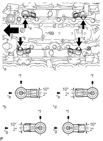
Install the 4 knock sensors with the 4 bolts so that the sensors are angled as shown in the illustration.

Torque:
20 N*m (204 kgf*cm, 15 ft.*lbf)

Text in Illustration
*a Bank 2 Sensor 1
*b Bank 1 Sensor 1
*c Bank 2 Sensor 2
*d Bank 1 Sensor 2
*e Front
*f Upper
*g Rear

NOTICE:

The acceptable installation angle of the knock sensor is between 10° upward and 2° downward from the horizontal position.


b.

Connect the 4 knock sensor connectors.


Hide 12215 2.INSTALL SEPARATOR CASE

a.

Install the separator case with the 4 bolts.

Torque:
10 N*m (102 kgf*cm, 7 ft.*lbf)


Hide 16297 3.CONNECT NO. 9 WATER BY-PASS HOSE
a.
A313311E02
1.396,0.448 1.438,0.198 1.438,0.198 1.51,0.198 true 1.792,1.313 1.573,1.615 1.573,1.615 1.5,1.615 true 1.281,1.521 1.5,1.729 0.219,0.208 10 true *a 1.51,0.094 1.698,0.26 0.188,0.167 10 false *a

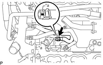
Connect the No. 9 water by-pass hose to the separator case, and slide the clamp to secure the hose.

Text in Illustration
*a Blue Mark

HINT:

Make sure the hose color matches the connection area color.


Hide 16293 4.CONNECT NO. 10 WATER BY-PASS HOSE
a.
A313312E02
1.396,0.448 1.438,0.198 1.438,0.198 1.51,0.198 true 1.802,1.583 1.583,1.885 1.583,1.885 1.521,1.885 true 1.292,1.792 1.479,1.958 0.188,0.167 10 true *a 1.51,0.094 1.698,0.26 0.188,0.167 10 false *a

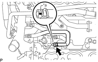
Connect the No. 10 water by-pass hose to the separator case, and slide the clamp to secure the hose.

Text in Illustration
*a Green Mark

HINT:

Make sure the hose color matches the connection area color.


Hide 17111 5.INSTALL INTAKE MANIFOLD