3UR-FE ENGINE CONTROL AIR FUEL RATIO SENSOR INSTALLATION
CAUTION / NOTICE / HINT
- HINT:
-
Perform "Inspection After Repairs" after replacing the air fuel ratio sensor (See page Engine / Hybrid System>3UR-FE ENGINE CONTROL>SFI SYSTEM>INITIALIZATION).
PROCEDURE

 89467B
1.INSTALL AIR FUEL RATIO SENSOR (for Bank 2 Sensor 1)
- HINT:
-
Perform "Inspection After Repairs" after replacing the air fuel ratio sensor (See page Engine / Hybrid System>3UR-FE ENGINE CONTROL>SFI SYSTEM>INITIALIZATION).
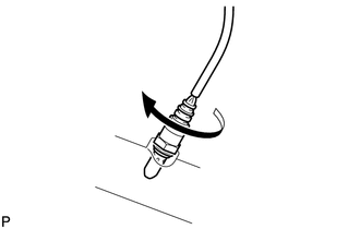
Install the air fuel ratio sensor to the exhaust pipe assembly by hand.
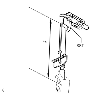
Using SST, tighten the air fuel ratio sensor sensor.
- SST
- 09224-00010
- Torque:
- without SST : 44 N*m (449 kgf*cm, 32 ft.*lbf)
- with SST : 40 N*m (408 kgf*cm, 30 ft.*lbf)
| *a | Fulcrum length |
- HINT:
- ·
Use a torque wrench with a fulcrum length of 30 cm (11.8 in.). If using a torque wrench with a length that is not 30 cm (11.8 in.), calculate the torque specification for the torque wrench and SST based on the "without SST" torque specification (See page General>INTRODUCTION>REPAIR INSTRUCTION>PRECAUTION).
·Make sure SST and the wrench are connected in a straight line.
89467B
2.INSTALL AIR FUEL RATIO SENSOR (for Bank 1 Sensor 1)
- HINT:
-
Perform "Inspection After Repairs" after replacing the air fuel ratio sensor (See page Engine / Hybrid System>3UR-FE ENGINE CONTROL>SFI SYSTEM>INITIALIZATION).
Install the air fuel ratio sensor to the front No. 2 exhaust pipe assembly by hand.
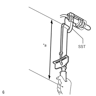
Using SST, tighten the air fuel ratio sensor.
- SST
- 09224-00010
- Torque:
- without SST : 44 N*m (449 kgf*cm, 32 ft.*lbf)
- with SST : 40 N*m (408 kgf*cm, 30 ft.*lbf)
| *a | Fulcrum length |
- HINT:
- ·
Use a torque wrench with a fulcrum length of 30 cm (11.8 in.). If using a torque wrench with a length that is not 30 cm (11.8 in.), calculate the torque specification for the torque wrench and SST based on the "without SST" torque specification (See page General>INTRODUCTION>REPAIR INSTRUCTION>PRECAUTION).
·Make sure SST and the wrench are connected in a straight line.
17410
3.INSTALL FRONT EXHAUST PIPE ASSEMBLY
Install a new gasket and the front exhaust pipe assembly to the exhaust manifold RH with 3 new nuts.
- Torque:
- 54 N*m (551 kgf*cm, 40 ft.*lbf)
Install a new gasket and the front exhaust pipe assembly to the center exhaust pipe assembly with the 2 bolts.
- Torque:
- 48 N*m (489 kgf*cm, 35 ft.*lbf)
Connect the air fuel ratio sensor connector.
Attach the 2 clamps and connect the heated oxygen sensor connector.
17450B
4.INSTALL FRONT NO. 2 EXHAUST PIPE ASSEMBLY
Connect the front No. 2 exhaust pipe assembly to the exhaust pipe support.
Install a new gasket and the front No. 2 exhaust pipe assembly to the exhaust manifold LH with 3 new nuts.
- Torque:
- 54 N*m (551 kgf*cm, 40 ft.*lbf)
Install a new gasket and the front No. 2 exhaust pipe assembly to the center exhaust pipe with the 2 bolts.
- Torque:
- 48 N*m (489 kgf*cm, 35 ft.*lbf)
Connect the air fuel ratio sensor connector.
Connect the heated oxygen sensor connector.
37140
5.INSTALL FRONT PROPELLER SHAFT ASSEMBLY (for 4WD)
37117
6.INSTALL PROPELLER SHAFT HEAT INSULATOR (for 4WD)
7.INSPECT FOR EXHAUST GAS LEAK