3UR-FBE ENGINE CONTROL SFI SYSTEM P0461 Fuel Level Sensor "A" Circuit Range / Performance P0462 Fuel Level Sensor "A" Circuit Low P0463 Fuel Level Sensor "A" Circuit High
DESCRIPTION
The fuel sender gauge is located inside the fuel tank and measures the amount of fuel. The fuel sender gauge converts the fuel level in the fuel tank into a resistance value, and outputs this value. The ECM determines when it is necessary to refuel the vehicle based on changes in the resistance value of the fuel sender gauge.
| DTC No. | DTC Detection Condition | Trouble Area |
|---|---|---|
| P0461 | Despite consuming a certain amount of fuel, the change in the resistance value of the fuel sender gauge is below the threshold.
(1 trip detection logic) |
·
Open or short in fuel sender gauge circuit ·
Fuel sender gauge assembly |
| P0462 | The resistance value of the fuel sender gauge is below the threshold.
(2 trip detection logic) |
·
Open or short in fuel sender gauge circuit ·
Fuel sender gauge assembly |
| P0463 | The resistance value of the fuel sender gauge exceeds the threshold.
(2 trip detection logic) |
·
Open or short in fuel sender gauge circuit ·
Fuel sender gauge assembly |
MONITOR DESCRIPTION
The ECM monitors the sensor resistance and uses this value to determine the amount of fuel remaining. When the sensor output resistance deviates from the normal operating range, the ECM determines that there is a malfunction in the fuel sender gauge and stores a DTC.
MONITOR STRATEGY
| Related DTCs | P0461: Fuel level sensor stuck
P0462: Fuel level sensor range check (Low Resistance) P0463: Fuel level sensor range check (High Resistance) |
| Required sensors/Components | Fuel sender gauge |
| Frequency of operation | Continuous |
| Duration | 10 seconds: P0461
30 seconds: P0462, P0463 |
| MIL operation | 1 driving cycle: P0461
2 driving cycles: P0462, P0463 |
| Sequence of operation | None |
TYPICAL ENABLING CONDITIONS
| Monitor runs whenever following DTCs not stored | None |
| Battery voltage | 8 V or higher |
| Ignition switch | ON |
| Lost communication with IPC control module (U0155) | Not detected |
| Monitor runs whenever following DTCs not stored | None |
| Battery voltage | 8 V or higher |
| Ignition switch | ON |
| Time after ignition switch turned from off to ON | 2 seconds or more |
| Starter | OFF |
| Vehicle speed | 40 km/h (24.86 mph) or higher for 30 seconds or more |
| Vehicle speed sensor circuit failure (P0500) | Not detected |
| Lost communication with IPC control module (U0155) | Not detected |
TYPICAL MALFUNCTION THRESHOLDS
| The difference between the fuel level sensor maximum and fuel level sensor minimum is less than 5 L | The cumulative volume of injected fuel 20 L or more (at low fuel level), 16 L or more (at middle fuel level) or 37.5 L or more (at high fuel level) |
| The difference between the fuel level sensor maximum and fuel level sensor minimum is less than 6.6 L | The cumulative volume of injected fuel 26 L or more (at low fuel level), 17.5 L or more (at middle fuel level) or 50.5 L or more (at high fuel level) |
| Fuel sender gauge resistance | Less than 35 Ω |
| Fuel sender gauge resistance | More than 816 Ω |
COMPONENT OPERATING RANGE
| Fuel sender gauge resistance | Varies between 35 and 816 Ω |
CONFIRMATION DRIVING PATTERN
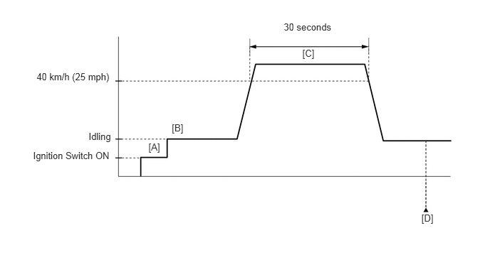
Connect the Techstream to the DLC3.
Turn the ignition switch to ON and turn the Techstream on.
Clear DTCs (even if no DTCs are stored, perform the clear DTC procedure).
Turn the ignition switch off and wait for at least 30 seconds.
Turn the ignition switch to ON and turn the Techstream on [A].
Start the engine [B].
Drive the vehicle at 40 km/h (25 mph) or more for 30 seconds or more [C].
Enter the following menus: Powertrain / Engine and ECT / Trouble Codes [D].
Read pending DTCs.
- HINT:
- ·
If a pending DTC is output, the system is malfunctioning.
·If a pending DTC is not output, perform the following procedure.
Enter the following menus: Powertrain / Engine and ECT / Utility / All Readiness.
Input the DTC: P0461, P0462 or P0463.
Check the DTC judgment result.
| Techstream Display | Description |
|---|---|
| NORMAL | ·
DTC judgment completed ·
System normal |
| ABNORMAL | ·
DTC judgment completed ·
System abnormal |
| INCOMPLETE | ·
DTC judgment not completed ·
Perform driving pattern after confirming DTC enabling conditions |
| N/A | ·
Unable to perform DTC judgment ·
Number of DTCs which do not fulfill DTC preconditions has reached ECU memory limit |
- HINT:
- ·
If the judgment result shows NORMAL, the system is normal.
·If the judgment result shows ABNORMAL, the system has a malfunction.
If the test result is INCOMPLETE or N/A and no pending DTC is output, perform a universal trip and check for permanent DTCs (See page Engine / Hybrid System>3UR-FBE ENGINE CONTROL>SFI SYSTEM>DTC CHECK / CLEAR).
- HINT:
- ·
When P0461 is output and the result does not change from INCOMPLETE or N/A, check whether the fuel receiver gauge of the combination meter operates after refueling the vehicle.
·If a permanent DTC is output, the system is malfunctioning.
·If no permanent DTC is output, the system is normal.
WIRING DIAGRAM
Refer to DTC B1500 (See page Vehicle Interior>METER / GAUGE / DISPLAY>METER / GAUGE SYSTEM>B1500).
CAUTION / NOTICE / HINT
Read freeze frame data using the Techstream. Freeze frame data records the engine condition when malfunctions are detected. When troubleshooting, freeze frame data can help determine if the vehicle was moving or stationary, if the engine was warmed up or not, if the air-fuel ratio was lean or rich, and other data from the time the malfunction occurred.
PROCEDURE
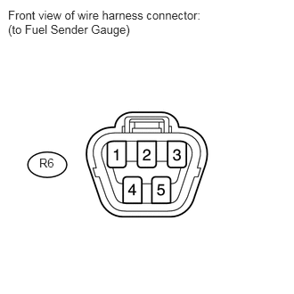
Disconnect the R6 fuel sender gauge assembly connector.
Turn the ignition switch to ON.
Measure the voltage according to the value(s) in the table below.
- Standard Voltage:
Tester Connection Switch Condition Specified Condition R6-2 - R6-3 Ignition switch to ON 11 to 14 V
OK
NG
Inspect the fuel sender gauge assembly (See page Engine / Hybrid System>3UR-FBE FUEL>FUEL SENDER GAUGE ASSEMBLY>INSPECTION).
OK
NG
Connect the Techstream to the DLC3.
Turn the ignition switch to ON.
Turn the Techstream on.
Drive the vehicle in accordance with the driving pattern described in Confirmation Driving Pattern.
Make sure that the Data List item "Alcohol Density Learning" is "Compl".
Enter the following menus: Powertrain / Engine and ECT / Data List / Alcohol Density Estimate, Short FT and Long FT.
Check the data list values, and then write them down.
NEXT
Confirm the alcohol concentration in the fuel (See page Engine / Hybrid System>3UR-FBE FUEL>FUEL SYSTEM>ON-VEHICLE INSPECTION).
Write down the alcohol concentration in the fuel.
NEXT
Use the following formula to calculate the difference between the learned value from step *1 and the actual alcohol concentration in the fuel from step *2.
- HINT:
-
[ (Alcohol Density Estimate / 2) - (Alcohol Concentration in Fuel / 2) ] < 10%
| Result | Proceed to |
|---|---|
| Difference is 10% or more | A |
| Difference is less than 10% | B |
A
B
Use the following formula to calculate the difference between the learned values from step *1 and the actual alcohol concentration in the fuel from step *2.
- HINT:
-
[ ((Alcohol Density Estimate / 2) + Short FT + Long FT) - (Alcohol Concentration in Fuel / 2) ] < 35%
| Result | Proceed to |
|---|---|
| Difference is 35% or more | A |
| Difference is 11 to 34% | B |
| Difference is 10% or less | C |
A
B
C
Check the fuel injection system (See page Engine / Hybrid System>3UR-FBE ENGINE CONTROL>SFI SYSTEM>Fuel Injection System).
- HINT:
-
If the problem area cannot be determined by checking the fuel injection system, proceed to the next step.
NEXT
Confirm the actual alcohol concentration in the fuel from step *2.
| Result | Proceed to |
|---|---|
| Alcohol concentration is more than 20% | A |
| Alcohol concentration is 20% or less | B |
A
B
Replace the fuel with E0 gasoline (replace approximately 20 liters (5 gallons) of fuel).
Connect the Techstream to the DLC3.
Turn the ignition switch to ON.
Turn the Techstream on.
Enter the following menus: Powertrain / Engine and ECT / Utility / Fuel Density Learning Value Reset.
Confirm the following conditions as instructed on the screen.
Ignition switch: ON
Engine: stopped
Battery voltage: 9 V or higher
After confirming, select "Next" and initialize the learned value.
- HINT:
-
If a message indicating learned value initialization failure is displayed on the screen, confirm the execution conditions, and perform learned value initialization again.
Turn the ignition switch off and wait for at least 30 seconds.
- NOTICE:
-
Proceed to the next step without starting the engine after performing "Learning Value Reset".
NEXT
Connect the Techstream to the DLC3.
Turn the ignition switch to ON.
Turn the Techstream on.
Enter the following menus: Powertrain / Engine and ECT / Utility / Learning Value Reset.
Confirm the following conditions as instructed on the screen.
Ignition switch: ON
Engine: stopped
Battery voltage: 9 V or higher
After confirming, select "Next" and initialize the learned value.
- HINT:
-
If a message indicating learned value initialization failure is displayed on the screen, confirm the execution conditions, and perform learned value initialization again.
Turn the ignition switch off and wait for at least 30 seconds.
Add at least 8 liters (2 gallons) of fuel.
- HINT:
-
Check "Fuel Remaining Volume" in the Data List and if it has a value of 85% or more, remove enough fuel so that the value decreases to less than 85% before adding fuel.
Turn the ignition switch to ON.
Enter the following menus: Powertrain / Engine and ECT / Data List / Alcohol Density learning.
Make sure that the Data List item "Alcohol Density Learning" is "Incmpl".
NEXT
Connect the Techstream to the DLC3.
Turn the ignition switch to ON.
Turn the Techstream on.
Enter the following menus: Powertrain / Engine and ECT / Utility / Fuel Density Learning Value Reset.
- HINT:
- ·
After clearing the learned value, the engine may become difficult to start if the concentration of alcohol in the fuel is high. Therefore, it may be necessary to crank the engine a few times before it starts.
·If "Fuel Density Learning Value Reset" is performed after warming the engine coolant up to approximately 50°C (122°F), the engine becomes easier to start afterward.
Confirm the following conditions as instructed on the screen.
Ignition switch: ON
Engine: stopped
Battery voltage: 9 V or higher
Press "Next".
When "Next" is pressed, initialization is performed automatically.
Turn the ignition switch off.
Add at least 8 liters (2 gallons) of fuel.
- NOTICE:
-
Add fuel immediately after resetting. (Do not start the engine before adding fuel.)
- HINT:
- ·
Learning of the alcohol concentration will not be started until the ECM judges that the fuel gauge has moved after resetting. Add at least 8 liters (2 gallons) of fuel.
·Check "Fuel Remaining Volume" in the Data List and if it has a value of 85% or more, remove enough fuel so that the value decreases to less than 85% before adding fuel.
Turn the ignition switch to ON.
Enter the following menus: Powertrain / Engine and ECT / Data List / Alcohol Density learning.
Make sure that the Data List item "Alcohol Density Learning" is "Incmpl".
NEXT
- HINT:
-
If the difference between the learned value of the vehicle from step *1 and the actual alcohol concentration in the fuel from step *2 is less than 10%, it is not necessary to perform learning.
Drive the vehicle in accordance with the driving pattern described in Confirmation Driving Pattern.
Make sure that the Data List item "Alcohol Density Learning" is "Compl".
Enter the following menus: Powertrain / Engine and ECT / Data List / Alcohol Density Estimate, Short FT and Long FT.
Check the data list values, and then write them down.
Confirm the alcohol concentration in the fuel (See page Engine / Hybrid System>3UR-FBE FUEL>FUEL SYSTEM>ON-VEHICLE INSPECTION).
Write down the alcohol concentration in the fuel.
Use the following formula to calculate the difference between the current learned value and the actual alcohol concentration in the fuel.
- HINT:
-
[ (Alcohol Density Estimate / 2) - (Alcohol Concentration in Fuel / 2) ] < 10%
- OK:
Result Specified Condition Difference between actual alcohol concentration and Alcohol Density Estimate Less than 10% Short FT and Long FT Between -35% and 35%
OK
NG
Disconnect the J28 meter connector.
Disconnect the R6 gauge connector.
Measure the resistance according to the value(s) in the table below.
- Standard Resistance:
Tester Connection Condition Specified Condition J28-26 (L) - R6-2 Always Below 1 Ω J28-25 (E3) - R6-3 J28-24 (ES) - Body ground J28-26 (L) or R6-2 - Body ground Always 10 kΩ or higher J28-25 (E3) or R6-3 - Body ground
OK
NG